
Shoulder belt clip for child safety seats and child carriers

a technology for child safety seats and shoulder belts, which is applied in the direction of safety belts, chairs, pedestrian/occupant safety arrangements, etc., can solve the problems of allowing occupants to escape all together, slipping connectors along the belts, and affecting the effectiveness of the restraint system, so as to prevent the harness from disengaging

Inactive Publication Date: 2006-12-05
HARCOURT JOHN A +1
View PDF16 Cites 14 Cited by
  • Summary
  • Abstract
  • Description
  • Claims
  • Application Information

AI Technical Summary

Benefits of technology

[0019]A purpose of the invention is to provide a child-resistant shoulder belt clip system for a child restraint harness comprising webbing shoulder straps. A preferred embodiment of the clip system serves to prevent disengagement of the harness as well as sliding of the clip along the webbing by the child occupant.
[0021]In a preferred embodiment, a narrowing of the U-shaped opening causes compression of the webbing between the tab and the opening, thereby preventing slippage of the clip vertically on the webbing that runs over both shoulders of the child. A lock that is preferably comprised of a spring-loaded slider is fixed between and disposed substantially parallel to the two straight slots and blocks the out-of-plane motion of the tab in the direction that would release the webbing, and also, by its positioning, prevents sliding the webbing laterally out the open end of the U-shaped opening. In a preferred embodiment, when release is desired by the parent, the lock slider is pushed back against the force of the spring and the flexible tab is pushed out-of-plane with respect to the body of the clip. This allows quick release of the webbing that runs over the right shoulder of the child.
[0026]In another preferred embodiment, the invention is a method for securing a child in a child safety seat, said method comprising: placing the child in the child safety seat; placing a left shoulder belt that is secured to the child safety seat over the left shoulder of the child; placing a right shoulder belt that is secured to the child safety seat over the right shoulder of the child; buckling a first portion of a buckle to which said left shoulder belt and a left lap belt extending over the left leg of the child are secured and buckling a second portion of a buckle to which said right shoulder belt and a right belt extending over the right leg of the child are secured to a third portion of said buckle to which a crotch belt is secured; adjusting a harness clip mounted on said left shoulder belt to about the chest level of the child, said harness clip having a U-shaped slot and comprising a slider that is biased in a locked position by a spring; retracting said slider and threading the right shoulder belt into the U-shaped slot with the right shoulder belt entering the top of said U-shaped slot from the back of the harness chip and entering the bottom of said U-shaped slot from the front of said U-shaped slot; and releasing said slider so that it moves to said locked position that prevents said right shoulder belt from being released from said U-shaped slot and from sliding in said U-shaped slot.

Problems solved by technology

The dangers inherent in these designs include the ease of manipulation of the harness clip by the child occupant, which undermine the efficacy of the restraint system or allow the occupants to escape all together.
Moreover, means are not provided to prevent slipping the connector along the belts.

Method used


Image

  • Shoulder belt clip for child safety seats and child carriers
  • Shoulder belt clip for child safety seats and child carriers
  • Shoulder belt clip for child safety seats and child carriers

Examples


Embodiment Construction

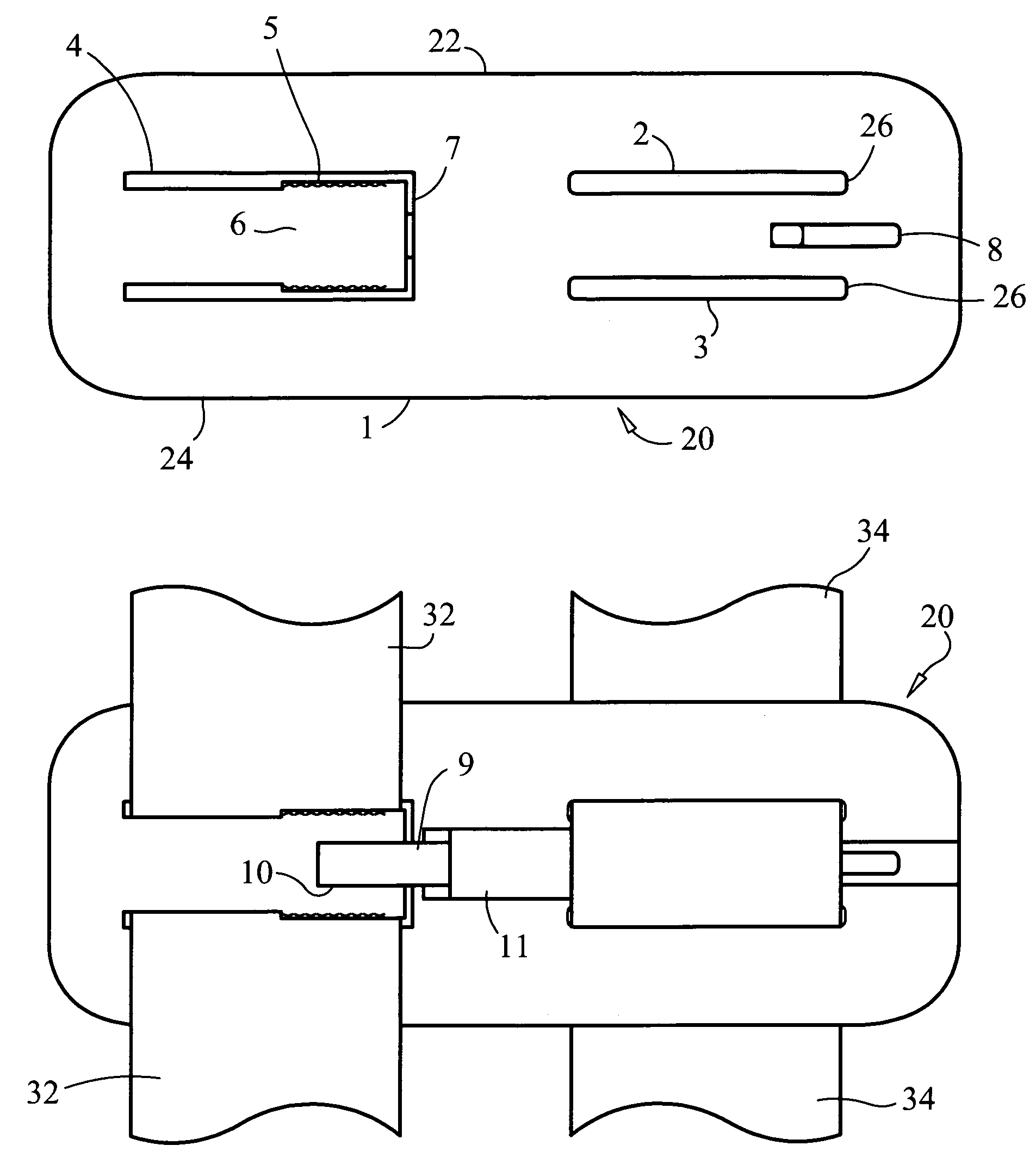
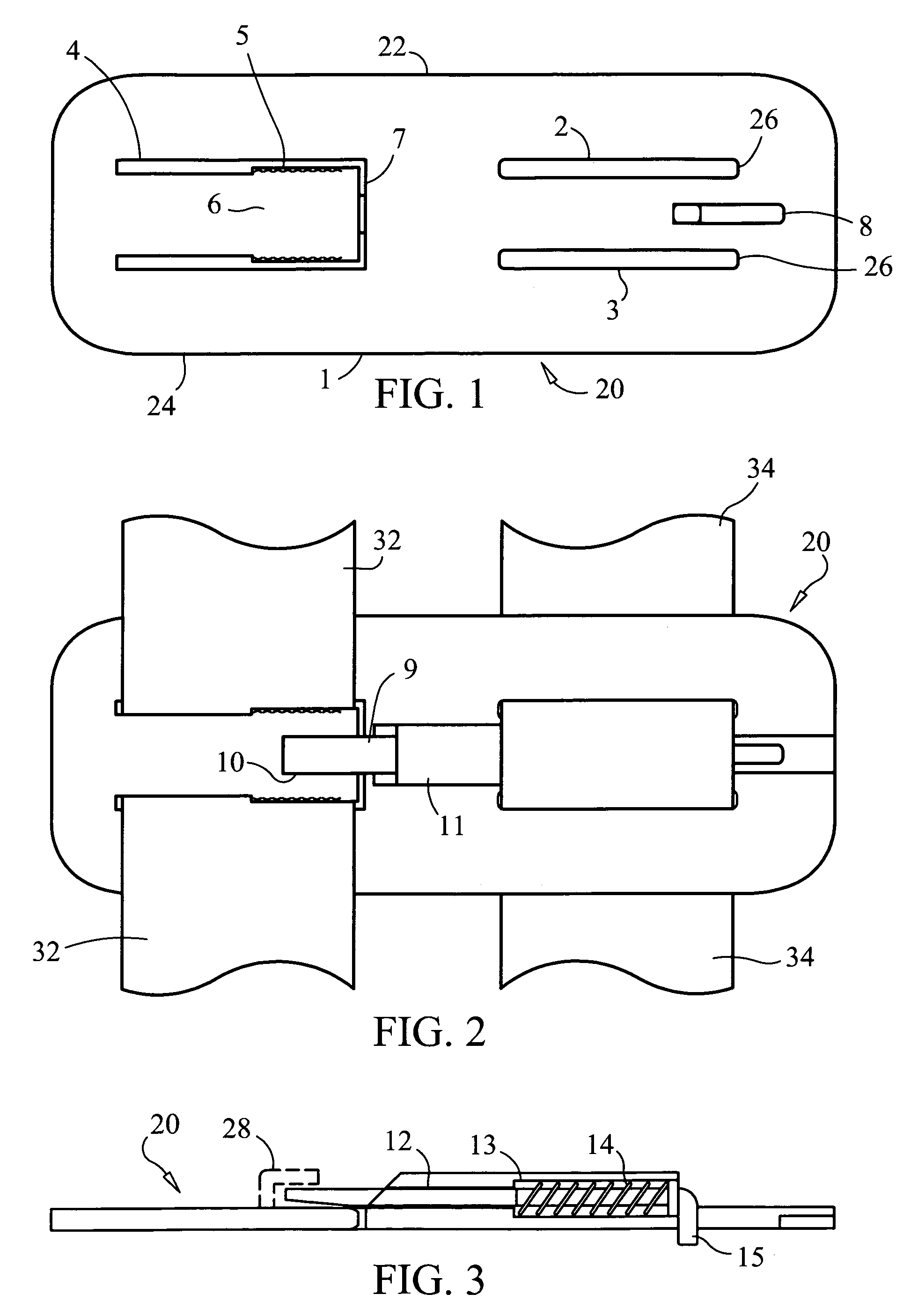
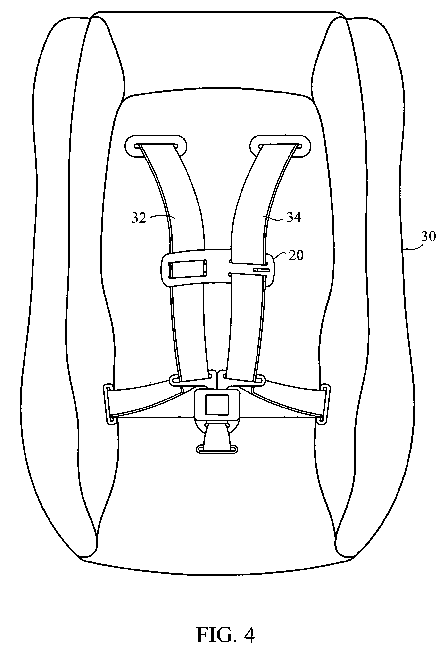
[0059]Referring to FIGS. 1 and 2, of a preferred embodiment of shoulder belt clip 20 is presented. Shoulder belt clip 20 is used in conjunction with the webbing portion of a harness for securing a child occupant in child safety seat or child carrier 30. The webbing portion comprises two belts, a first belt that is oriented substantially vertically and extends over one shoulder of the child occupant and a second belt that is oriented substantially vertically and extends over the other shoulder of the child when child safety seat or child carrier 30 is in use. When shoulder belt clip 20 is in use, it is oriented substantially horizontally and connects the first belt and the second belt at approximately the chest level of the child occupant.

[0060]In a preferred embodiment, shoulder belt clip 20 is comprised of plate 1 which is preferably made of flexible material, such as a thermoplastic, e.g., high density polyethylene or polypropylene. Plate 1 comprises first portion 22 and second po...


PUM


Abstract

A shoulder belt clip for restraining a child in a child safety seats or carrier. In a preferred embodiment, the shoulder belt clip is comprised of a plate made of flexible material and with two horizontal slots arranged in parallel on one side and a U-shaped opening on the other. The two straight slots maintain attachment to, but allow the clip to slide vertically on, the webbing that runs over the left shoulder of the child. The U-shaped opening forms a tab that admits entry of the webbing that runs over the right shoulder of the child and holds it until release is desired by the parent. A narrowing of the U-shaped opening causes compression of the webbing between the tab and the opening and thereby prevents slippage of the clip vertically on the webbing that runs over the left shoulder of the child. A lock comprised of a spring-loaded slider is fixed between and parallel to the two straight slots blocks the out-of-plane motion of the tab in the direction that would release the webbing, and also by its positioning prevents sliding the webbing laterally out the open end of the U-shaped opening. When release is desired by the parent, the lock slider is pushed back against the force of the spring and the flexible tab is pushed out-of-plane with respect to the body of the clip. This allows quick release of the webbing that runs over the right shoulder of the child.

Description

CROSS-REFERENCE TO RELATED APPLICATIONS[0001]This application claims the benefit of U.S. Provisional Patent Application No. 60 / 512,133, filed Oct. 17, 2003, pending, the disclosure of which application is incorporated by reference as if fully set forth hereinSTATEMENT REGARDING FEDERALLY SPONSORED RESEARCH OR DEVELOPMENT[0002]Not ApplicableBACKGROUND OF THE INVENTION[0003]This invention relates to shoulder clips for child restraints. In particular, the invention relates to shoulder clips for harness systems for child safety seats and child carriers.[0004]In the background art, the application of restraint webbing in child safety seats has involved use of approximately 1.5-inch wide loops of webbing in three-, four- and five-point configurations. These configurations rely on centrally located multiple-receiver buckles and a sliding harness clip to join them into a matrix that is meant to provide effective restraint during vehicle (e.g., automobile) collisions. The dangers inherent in...

Claims


Application Information

Patent Timeline
IPC IPC(8): A47F1/00A44B11/25A44B11/26A44B17/00A62B35/00
CPCB60N2/2812B60R22/105Y10T24/45602Y10T24/45623Y10T24/45529
Inventor HARCOURT, JOHN A.MUNSELL, JR., WILLIAM P.
Owner HARCOURT JOHN A
Learn More