Water well pump

a well pump and water well technology, applied in the direction of pump components, positive displacement liquid engines, liquid fuel engine components, etc., can solve the problems of water hammer development, certain problems in the operation of hard-working pumps, and home owners never give much thought to hard-working pumps. , to achieve the effect of reducing vibration, good cylinder for the piston, and quick closing of the valv

Inactive Publication Date: 2006-12-05
LOCHER BEN C
View PDF223 Cites 3 Cited by
  • Summary
  • Abstract
  • Description
  • Claims
  • Application Information

AI Technical Summary

Benefits of technology

[0025]It is another object of the present invention to provide a novel water well pump, which provides a built in hydraulic damper for the vibrations of the ball.
[0026]It is another object of the present invention to provide a novel water well pump with a crude inexpensive riser pipe, which serves well to not only carry the water upward, but also serves as a good cylinder for the piston.
[0027]It is another object of the present invention to provide a novel water well pump, which provides a large, free flowing labyrinthine path for the water moving through, giving the benefit of reduced vibrations by utilizing the hydraulic damping of vibrations of any fluid in labyrinthine pa

Problems solved by technology

Most well pumps last for years, and homeowners never give much thought to hard-working pumps that faithfully kick in every time a homeowner takes a shower, does laundry, or runs the dishwasher.
In spite of the relatively highly developed state of the art in reciprocating plunger well pumps, certain problems in the operation of these pumps persist.
In particular, when pumps are stopped, water hammer develops, which is an unwanted noisy and shaking condition of the pump.
Therefore, when the seat that the ball rests on becomes worn and damaged by the constant beating from the ball, erosion from a

Method used


Image

  • Water well pump
  • Water well pump
  • Water well pump

Examples


Embodiment Construction

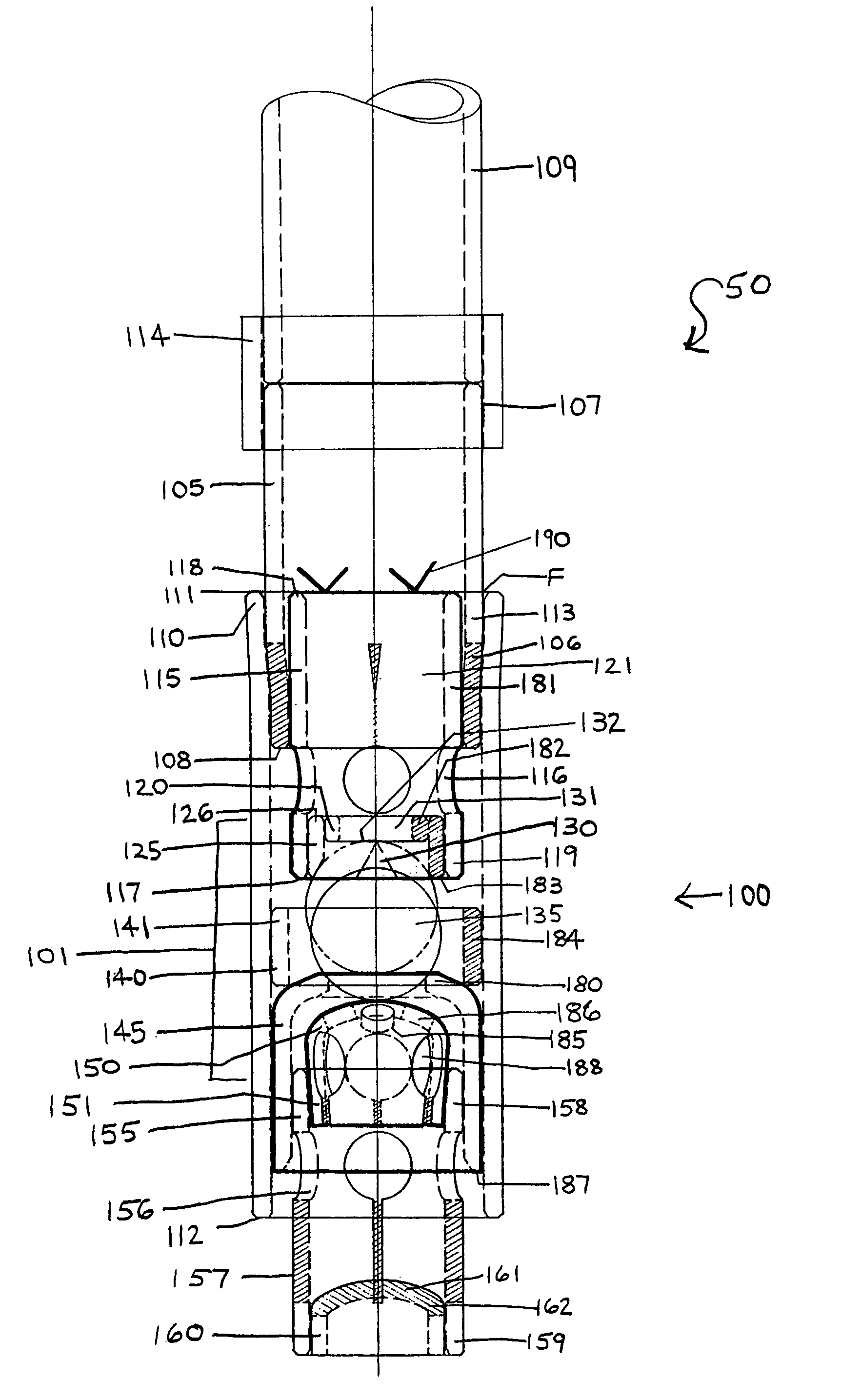
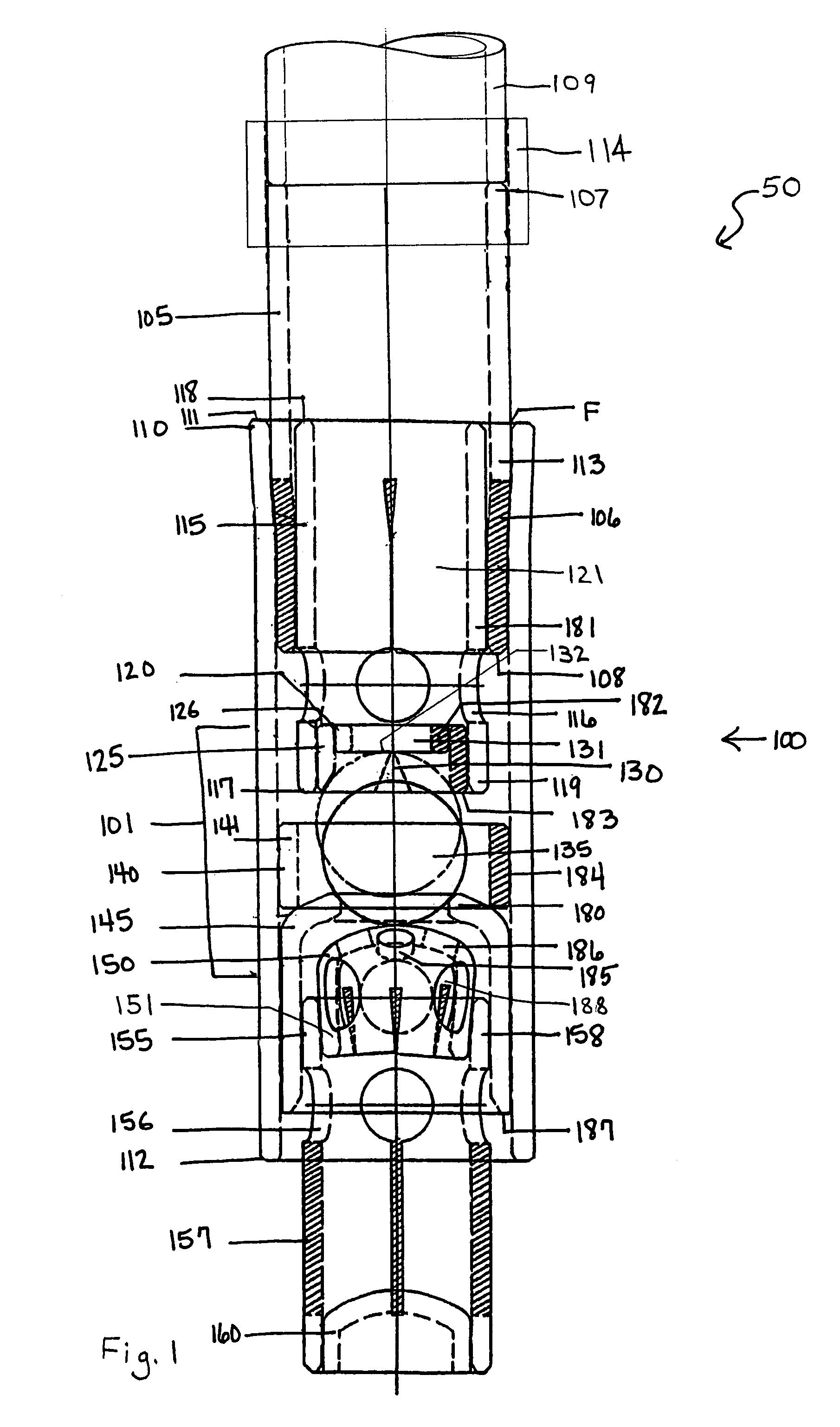
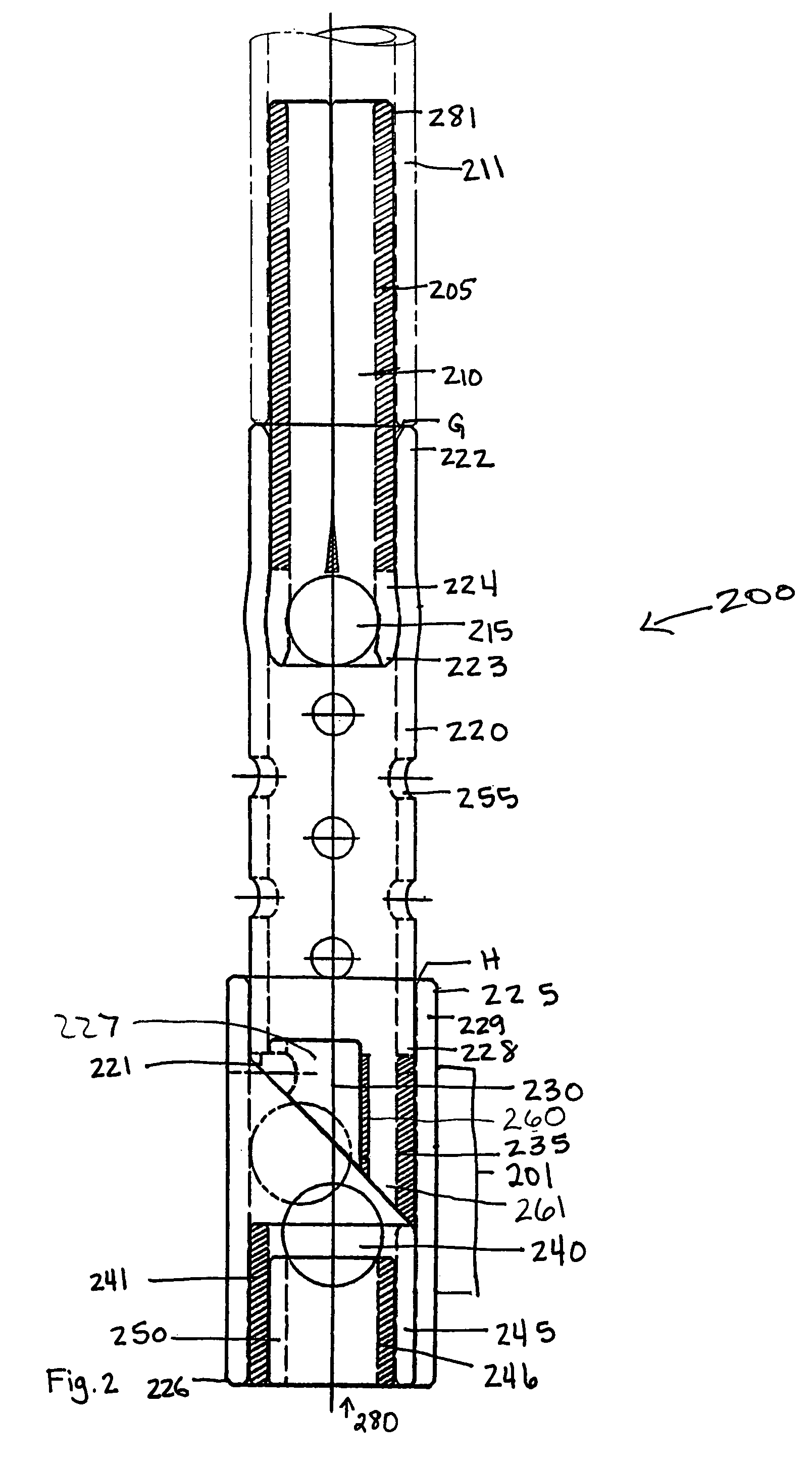
[0036]Referring to FIGS. 1 and 3, the standing valve holder of the water well pump of the preferred embodiment and of the second embodiment, respectively, of the present invention is shown. Referring to FIGS. 1 and 3, standing valve holder 100 contains a one-way standing valve 101. One-way standing valve 101 is composed of the lower end of piston stop 115, balcony seat 125, damper ring 120, twist notch 130, elastic ball 135, collar 140, main seat 145, and support 150, within shell 110.

[0037]Standing valve holder 100 contains an elongated shell 110 which is cylindrical having two open ends. Shell 110 is preferably fabricated of a high density polymer such as Schedule 40 PVC piping or ABS piping, but can be manufactured with any suitable material. In the preferred embodiment, shell 110 will have a 1½ inch inner diameter and will be about 13 cm in length. The two ends of shell 110 consist of an upper end 111 facing ground level and a lower end 112 facing the Earth's center when positio...


PUM


Abstract

The present invention contains a one-way standing valve holder and a one-way traveling valve holder. Contained within a shell of the standing valve holder are a nipple at the upper end and an intake tube at the lower end. A piston rod extends down from the earth's surface to the traveling valve holder. At the lower end of the release tube is a piston. The piston end of the traveling valve holder is inserted into the nipple end of standing valve holder aligning the piston with piston stop. An elastic ball within the shell creates a one-way standing valve, and a hard ball within the piston creates a one-way traveling valve. Surface equipment connected to traveling valve holder is used to reciprocate the pump up and down opening and closing the one-way valves at alternating intervals. Water fills into the riser pipe and additional pumping allows collection of water.

Description

[0001]This application claims priority to U.S. Provisional Application Ser. No. 60 / 430,901 filed Dec. 4, 2002.BACKGROUND OF THE INVENTION[0002]1. Field of the Invention[0003]The present invention relates generally to a water well pump.[0004]2. Background Information[0005]All too often, water is taken for granted. Most well pumps last for years, and homeowners never give much thought to hard-working pumps that faithfully kick in every time a homeowner takes a shower, does laundry, or runs the dishwasher. Well pumps are the modern day equivalent of windmills, which were used to move water from one place to another over one hundred years ago. Like windmills, well pumps are particularly handy for irrigating crops, providing livestock with water, supplying water to remote locations, or for acting as heating and cooling mechanisms for geothermal systems. There are two general types of well pumps: submersible and jet.[0006]About sixty percent of home wells in the U.S. use electric submersi...

Claims


Application Information

Patent Timeline
IPC IPC(8): F04B39/10F04B47/02F04B53/10F04B53/12
CPCF04B47/02F04B53/1002F04B53/126
Inventor LOCHER, BEN C.
Owner LOCHER BEN C
Why Eureka
Try Eureka