Permanent magnet type three-phase stepping motor

a permanent magnet and three-phase technology, applied in the direction of dynamo-electric converter control, magnetic circuit rotating parts, magnetic circuit shape/form/construction, etc., can solve the problems of increased cogging torque, increased vibration and cogging torque, and increased vibration and nois

Inactive Publication Date: 2006-12-05
JAPAN SERVO CO LTD
View PDF25 Cites 8 Cited by
  • Summary
  • Abstract
  • Description
  • Claims
  • Application Information

AI Technical Summary

Benefits of technology

[0018]The three-phase exiting is carried out with respect to the three-phase windings and a current passing through each of the three-phase windings is controlled so as to eliminate an unbalanced force in the radial direction.

Problems solved by technology

However, the vibration and the noise are generated even in the three-phase stepping motor, because many harmonic waves are generated in the magnetic flux field made by the permanent magnet under the affection of a number of pole teeth.
If such conventional stepping motor having three stator main poles is driven by the two-phase exciting manner, an unbalanced electromagnetic force is generated in the radial direction, and harmonic waves are generated due to the large number of small rotor teeth, so that the cogging torque is increased.
Further, the center of the air gap between the rotor and the stator is deviated due to the unbalanced electromagnetic force in the radial direction, so that the vibration and the cogging torque are also increased.
Accordingly, the error in the electrical angle becomes large even if the error in the mechanical angle is small.
Thus, the manufactured stepping motors become different from one another in cogging torque, vibration or noise.

Method used


Image

  • Permanent magnet type three-phase stepping motor
  • Permanent magnet type three-phase stepping motor
  • Permanent magnet type three-phase stepping motor

Examples


first embodiment

[0033]the present invention will now be explained with reference to the drawings.

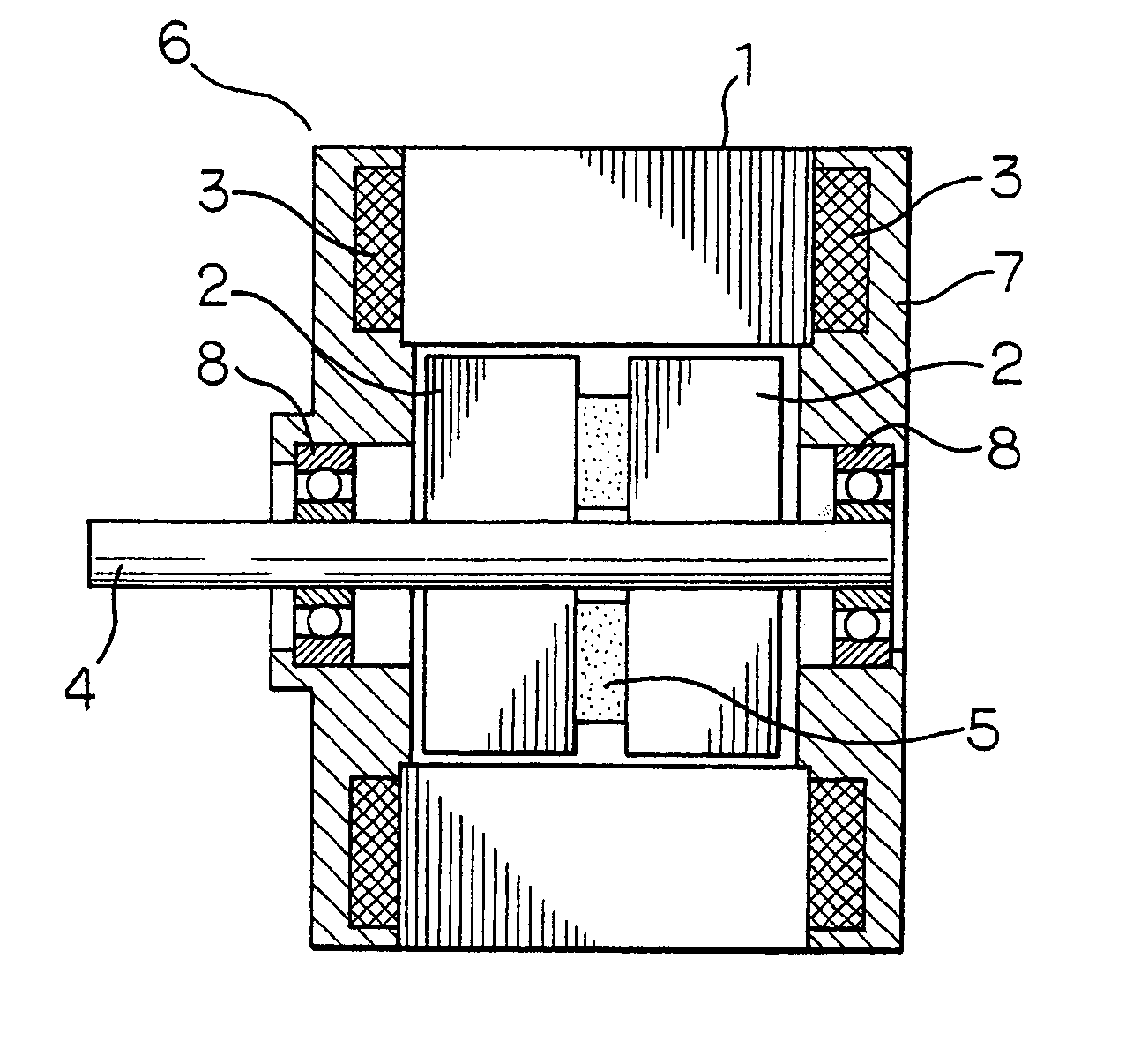
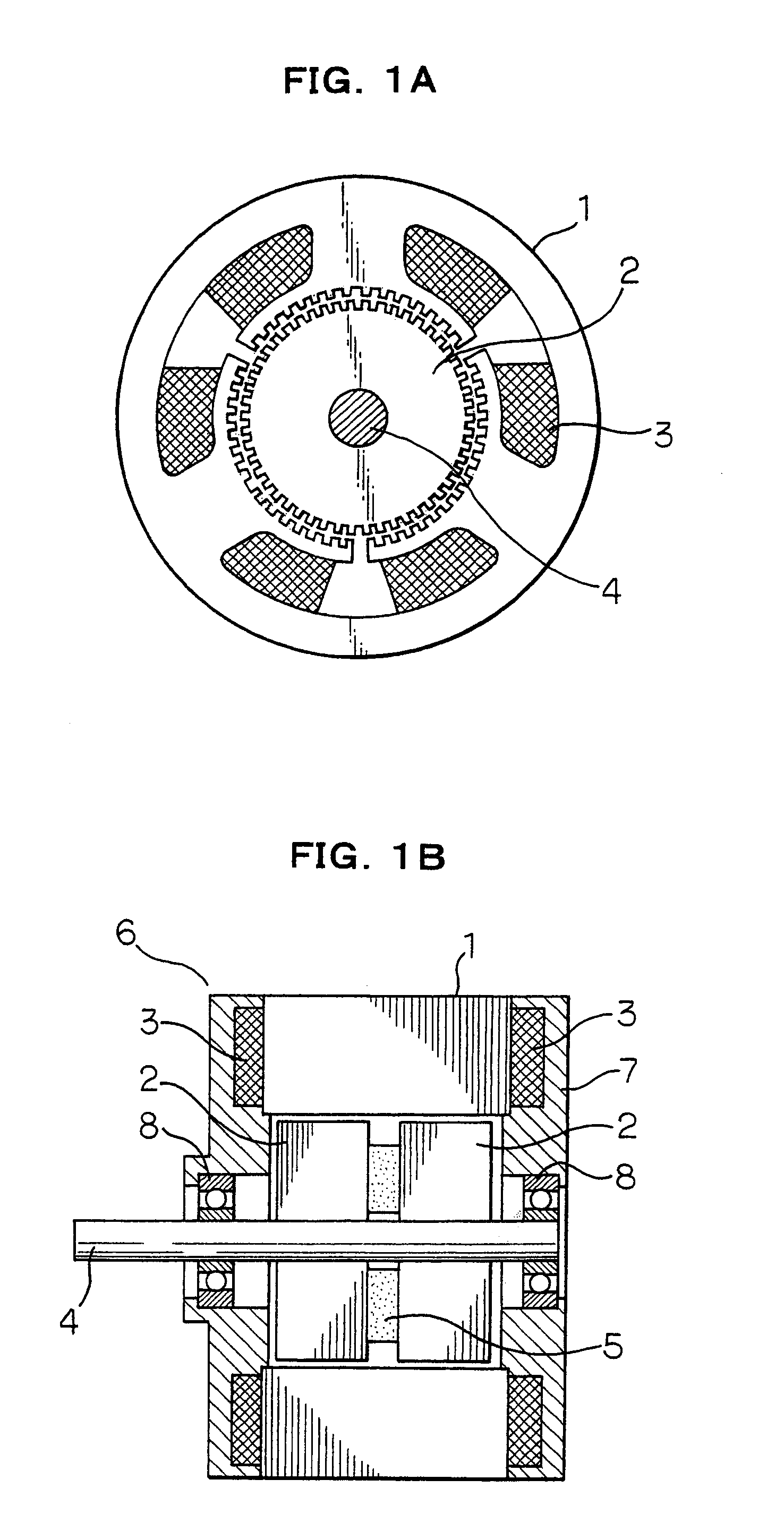
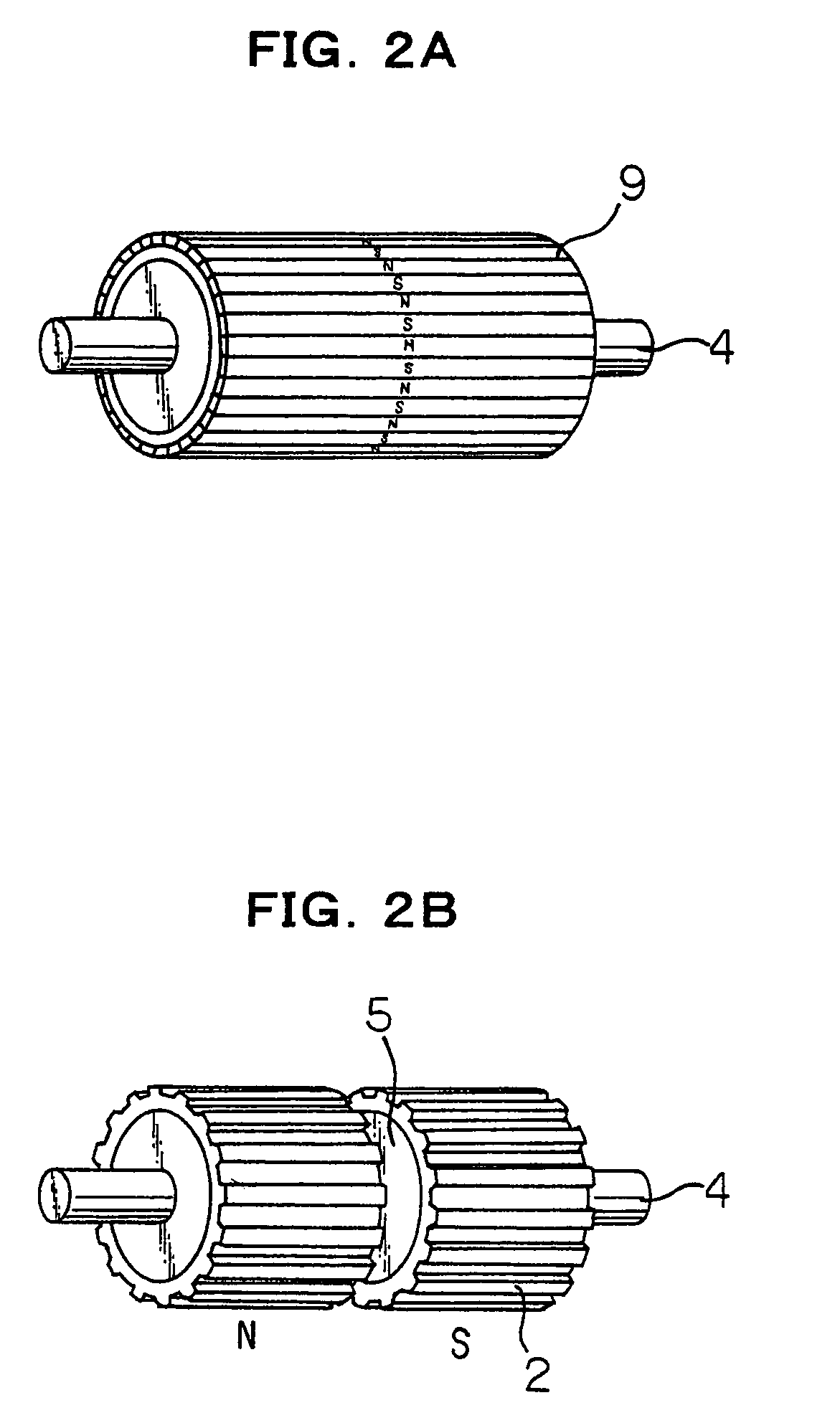
[0034]In FIG. 1A and FIG. 1B, a reference numeral 1 denotes a stator having three main poles, 2 denotes two magnetic rotor elements of hybrid type (HB), rotationally shifted from each other by a ½ tooth pitch in position of their magnetic teeth, 3 denotes windings each wound around each stator main pole for forming each phase, 4 denotes a rotor shaft, 5 denotes a permanent magnet held by the two magnetic rotor elements 2 and magnetized so as to form N and S poles in the axial direction thereof, 6 and 7 denote brackets of non-magnetic material, such as aluminum having portions extending in the axial direction for supporting the inner peripheral surface of the stator 1 so as to form an air gap between the stator 1 and the rotor 2, and 8 denotes bearings.

[0035]In the three-phase hybrid type stepping motor of the present invention, a pitch of stator pole teeth is set smaller than a pitch of the small rotor ...

second embodiment

[0038]the present invention will be explained. The harmonic wave in the air gap and the cogging torque due to the magnetic flux of the permanent magnet can be reduced, if the pitch of the stator pole teeth shown in FIG. 1A is set smaller than that of the small rotor teeth. In order to obtain a good result, it is necessary to know what kinds of harmonic wave are included in the cogging torque or torque which is generated when the windings of the permanent magnet type three-phase stepping motor are excited by electric current. It is noted, however, that the cogging torque of the three-phase stepping motor relates mainly to the sixth harmonic wave and the torque due to the current relates to the odd number harmonic wave.

[0039]Formula 5 shows the magnetic flux due to the permanent magnet for each phase in the three-phase stepping motor.

[0040]3⁢⁢P0>>Pm.⁢ΦA=(Pm⁢Fm / 3⁢P0)⁢PAΦB=(Pm⁢Fm / 3⁢P0)⁢PB}⁢⁢ΦC=(Pm⁢Fm / 3⁢P0)⁢PC(5)

Formula 6 shows permeances PA, PB, PC, {overscore (P)}A, {overscore (P)}B an...


PUM


Abstract

A permanent magnet type three-phase stepping motor that is simple in construction, with reduced vibration, a reduced unbalanced force in the radial direction, and high torque that can be manufactured at a low cost. The permanent magnet type three-phase stepping motor has a stator and a rotor arranged concentrically with the stator and with an air gap therebetween, said stator having three stator poles, and stator windings of three-phase each wound around each stator pole, each of said stator poles having m pieces of stator pole tooth, said rotor having two split rotor elements, a permanent magnet held between the rotor elements and magnetized so as to form N and S poles in the axial direction thereof, and a plurality (Nr) of small rotor teeth formed at a regular pitch on the outer peripheral surface of each of said rotor elements, said two split rotor elements being circumferentially shifted from each other by a ½ pitch of the small rotor teeth, wherein a pitch of the stator pole teeth is smaller than the pitch of the small rotor teeth, m is an integer and (Nr±2k) / 3, Nr is 3n±1, n is an integer not less than 1, and k is an integer not less than 1 and not more than 4.

Description

RELATED APPLICATION[0001]This application is a division of application Ser. No. 10 / 196,982 filed Jul. 17, 2002, now U.S. Pat. No. 6,903,476, which claims priority to Japanese Application No. 223010-2001 filed Jul. 24, 2001.BACKGROUND OF THE INVENTION[0002]1. Field of the Invention[0003]The present invention relates to a permanent magnet type three-phase stepping motor and, more particularly, to a permanent magnet type three-phase stepping motor for use in an apparatus for an office automation or the like.[0004]2. Description of the Prior Art[0005]The vibration generated in the permanent magnet type three-phase stepping motor is smaller than the vibration generated in the permanent magnet type two-phase stepping motor. The number of transistors required for the driving circuit of the three-phase stepping motor is six, whereas the number of transistors required for the driving circuit of the two-phase stepping motor is eight. Accordingly, the three-phase stepping motor is excellent in...

Claims


Application Information

Patent Timeline
Patent Type & Authority Patents(United States)
IPC IPC(8): H02K37/10H02K1/27H02K29/03H02K37/04H02K37/14H02P8/14
CPCH02K29/03H02K37/18H02P8/14
Inventor SAKAMOTO, MASAFUMI
Owner JAPAN SERVO CO LTD
Why Eureka
Try Eureka