Eureka AIR delivers breakthrough ideas for toughest innovation challenges, trusted by R&D personnel around the world.

Systems and methods for updating a frame buffer based on arbitrary graphics calls

a frame buffer and graphics call technology, applied in the field of computer graphics, can solve the problems of enormous processing resources consumed by this approach, inefficient method, resource-intensive approach, etc., and achieve the effect of significant performance gain

Inactive Publication Date: 2006-12-05
MICROSOFT TECH LICENSING LLC
View PDF14 Cites 23 Cited by
  • Summary
  • Abstract
  • Description
  • Claims
  • Application Information

AI Technical Summary

Benefits of technology

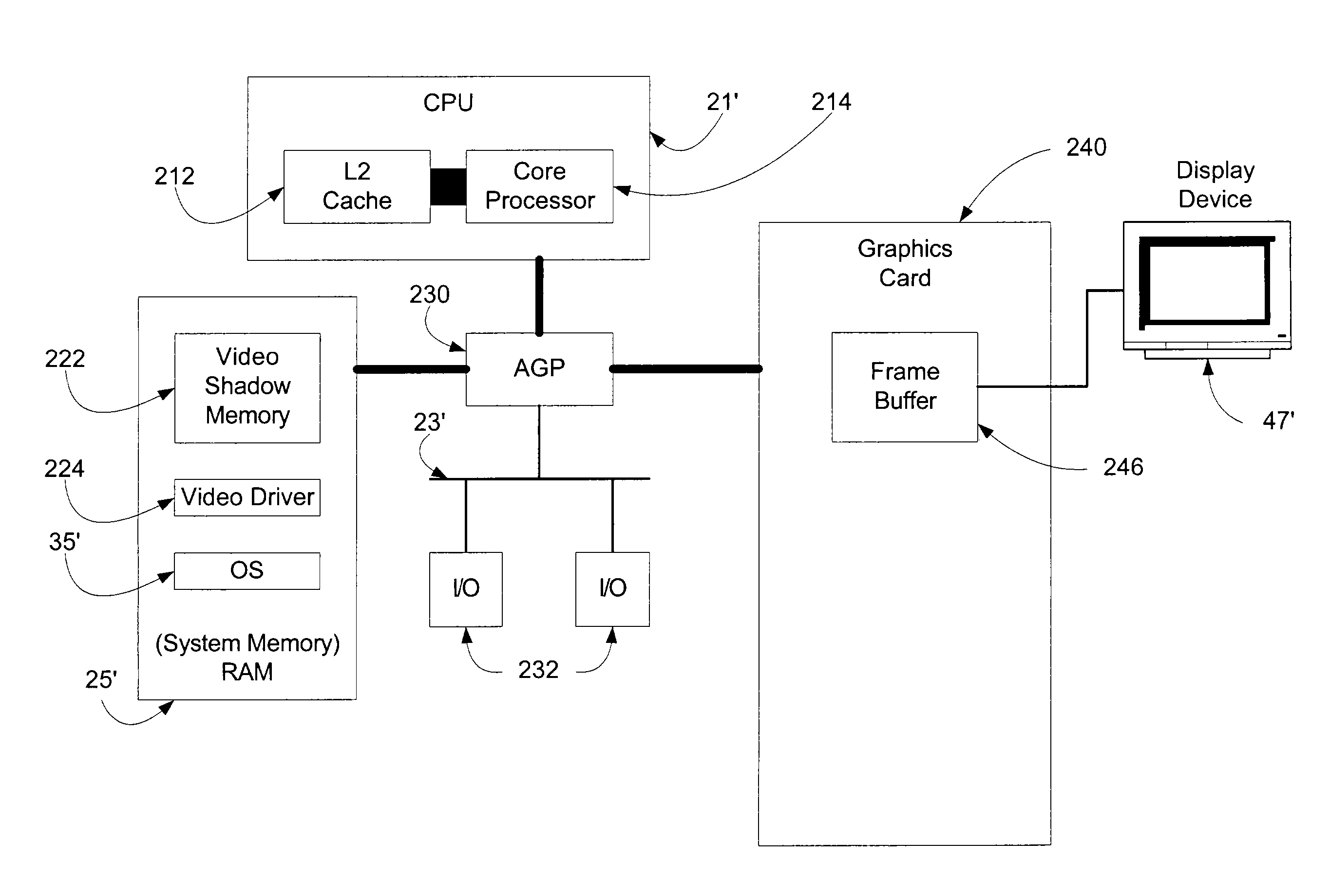
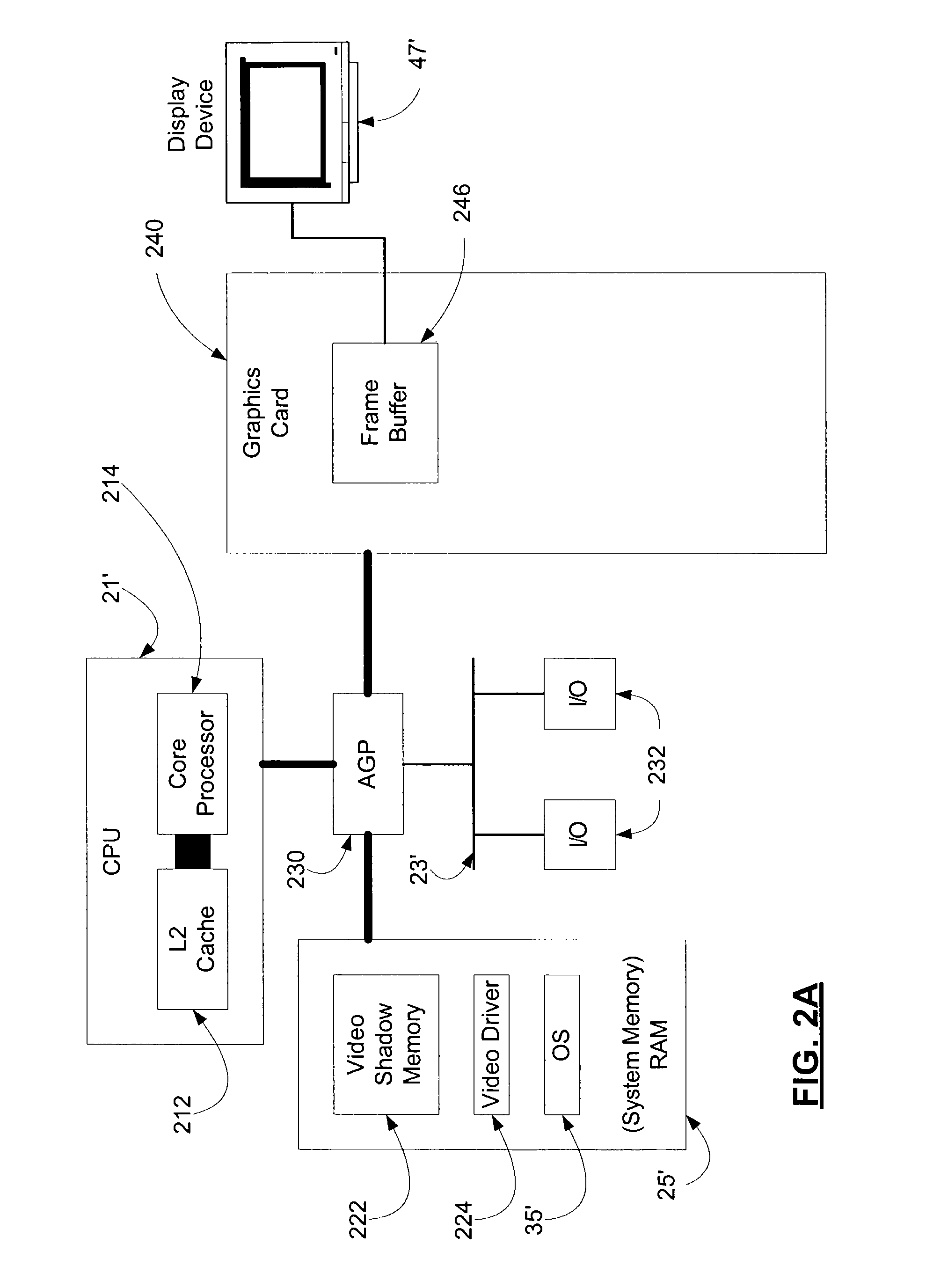
[0007]The method for one embodiment of the present invention is to establish the zone grid at system initialization and, thereafter, track which zones have any pixels revised so that, when the time comes to update the display, only the zones requiring revision (that is, those zones in which any pixel has been revised) are copied from shadow memory to the frame buffer for display on the display device. The memory for tracking these zones can be allocated at initialization and held since it is relatively small. As a result, a significant performance gain may be achieved by avoiding the shortcomings of the existing methods in the art notwithstanding the fact that some “clean” pixels in each zone having even a single changed pixel are also rewritten to the frame buffer.

Problems solved by technology

However, this method is extremely inefficient because every pixel of the display device is updated in the frame buffer whether the data for that pixel has changed or not, and the processing resources consumed by this approach are enormous.
This approach has the advantage of copying to the frame buffer data pertaining only to those pixels which have changed; however, this approach is also resource intensive in regard to the memory necessary for maintaining the revision list which, in the worst case scenario, may require a change to every pixel.
This, along with other shortcomings, significantly slows video processing.
However, for complex revisions, such as a curves and other shapes that can only be broken down into a very large number of small rectangular regions, conducting the merge (among other tasks) is very expensive computationally.

Method used


Image

  • Systems and methods for updating a frame buffer based on arbitrary graphics calls
  • Systems and methods for updating a frame buffer based on arbitrary graphics calls
  • Systems and methods for updating a frame buffer based on arbitrary graphics calls

Examples


Embodiment Construction

[0015]The subject matter is described with specificity to meet statutory requirements. However, the description itself is not intended to limit the scope of this patent. Rather, the inventors have contemplated that the claimed subject matter might also be embodied in other ways, to include different steps or combinations of steps similar to the ones described in this document, in conjunction with other present or future technologies. Moreover, although the term “step” may be used herein to connote different elements of methods employed, the term should not be interpreted as implying any particular order among or between various steps herein disclosed unless and except when the order of individual steps is explicitly described.

Computer Environment

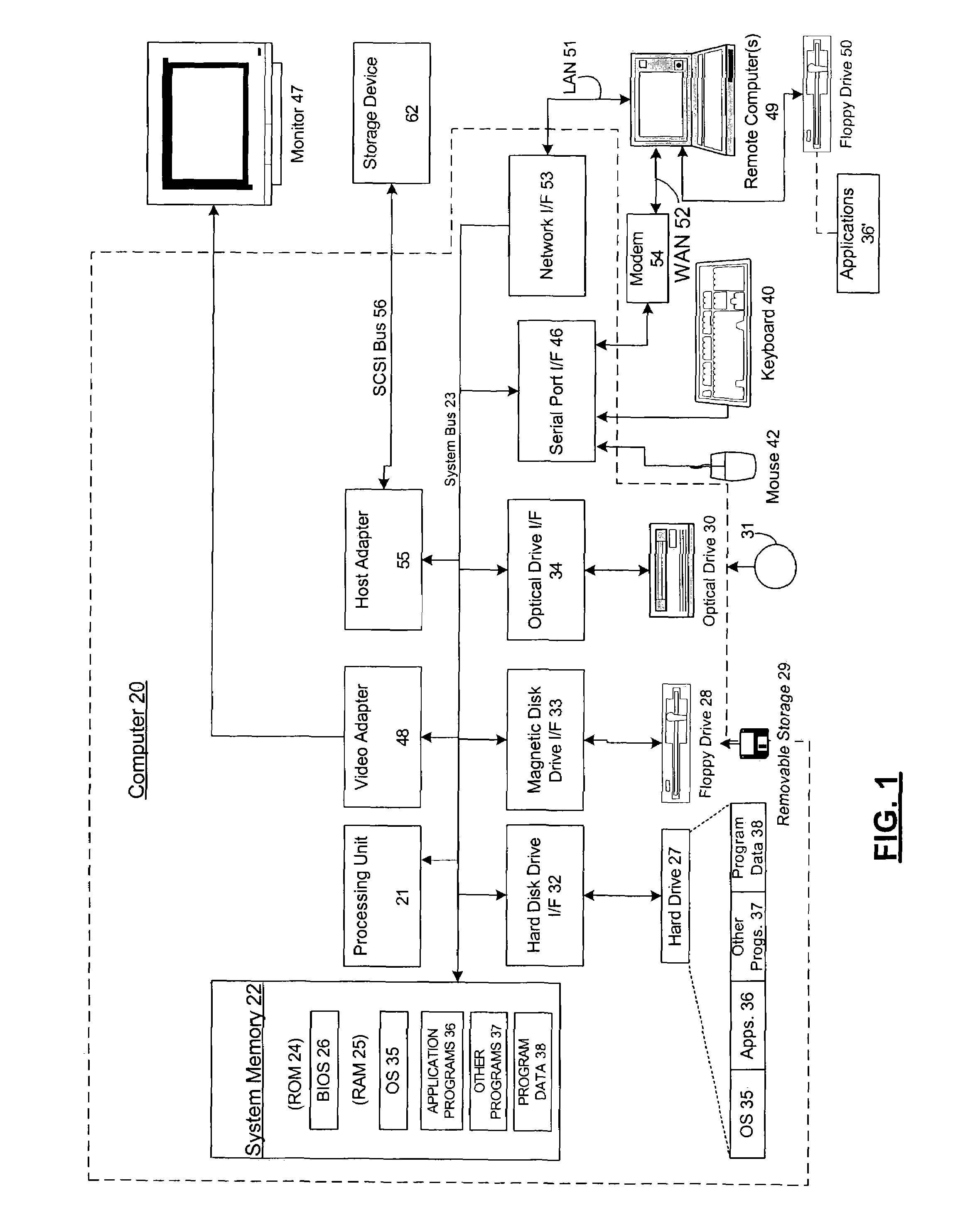
[0016]Numerous embodiments of the present invention may execute on a computer. FIG. 1 and the following discussion is intended to provide a brief general description of a suitable computing environment in which the invention may be implement...


PUM


Abstract

A method for dividing a display into zones at system initialization for tracking which zones have any pixels revised so that, when the time comes to update the display, only the zones requiring revision (that is, those zones in which any pixel has been revised) are copied from shadow memory to the frame buffer for display on the display device. The memory for tracking these zones can be allocated at initialization and held since it is relatively small. Consequently, a significant performance gain may be achieved by avoiding the shortcomings of the existing methods in the art notwithstanding the fact that some “clean” pixels in each zone having even a single changed pixel are also rewritten to the frame buffer.

Description

CROSS-REFERENCE TO RELATED APPLICATIONS[0001]This application is related by subject matter to the inventions disclosed in the following commonly assigned applications: U.S. patent application Ser. No. 10 / 623,220, filed on even date herewith, entitled “SYSTEMS AND METHODS FOR EFFICIENTLY DISPLAYING GRAPHICS ON A DISPLAY DEVICE REGARDLESS OF PHYSICAL ORIENTATION”; and U.S. patent application Ser. No. 10 / 622,597, filed on even date herewith, entitled “SYSTEMS AND METHODS FOR EFFICIENTLY UPDATING COMPLEX GRAPHICS IN A COMPUTER SYSTEM BY BY-PASSING THE GRAPHICAL PROCESSING UNIT AND RENDERING GRAPHICS IN MAIN MEMORY”.FIELD OF THE INVENTION[0002]The present invention relates generally to the field of computer graphics, and more particularly to the efficient generation and updating of computer graphics in a computer frame buffer for display on a display device.BACKGROUND OF THE INVENTION[0003]There are many approaches to updating graphics on a display device. One classic method, although ra...

Claims


Application Information

Patent Timeline
Patent Type & Authority Patents(United States)
IPC IPC(8): G06T1/60G06T1/00G09G5/36G09G5/00G09G5/393
CPCG09G5/393
Inventor KARLOV, DONALD DAVID
Owner MICROSOFT TECH LICENSING LLC
Why Eureka
Eureka Blog
Learn More