Lightweight heat sink

a heat sink and light-weight technology, applied in the direction of lighting and heating apparatus, semiconductor/solid-state device details, computerized elements, etc., can solve the problems of increasing complexity of circuit design, increasing the size of the device, and increasing the complexity of the design

Inactive Publication Date: 2006-12-12
PARKER INTANGIBLES LLC
View PDF66 Cites 46 Cited by
  • Summary
  • Abstract
  • Description
  • Claims
  • Application Information

AI Technical Summary

Problems solved by technology

Circuit designs for modem electronic devices such as televisions, radios, computers, medical instruments, business machines, communications equipment, and the like have become increasingly complex.
Although the complexity of the designs has increased, the size of the devices has continued to shrink with improvements in the ability to manufacture smaller electronic components and to pack more of these components in an ever smaller area.
As electronic components such as IC semiconductor chips or dies have become smaller and, in turn, more densely packed on printed circuit boards (PCBs), designers and manufacturers now are faced with the challenge of how to dissipate the heat which is ohmicly or otherwise generated by these components.
Indeed, it is well known that many electronic components, and especially power semiconductor components such as transistors and microprocessors, are more prone to failure or malfunction at high temperatures.
Thus, the ability to dissipate heat often is a limiting factor on the performance of the component.
However, these plastic materials generally exhibit less efficient heat transfer characteristics as compare to other package materials, and therefore may raise additional thermal dissipation considerations.
For high power circuits and the smaller but more densely packed circuits typical of current electronic designs, however, simple air circulation often has been found to be insufficient to adequately cool the circuit components.

Method used


Image

  • Lightweight heat sink
  • Lightweight heat sink
  • Lightweight heat sink

Examples


example

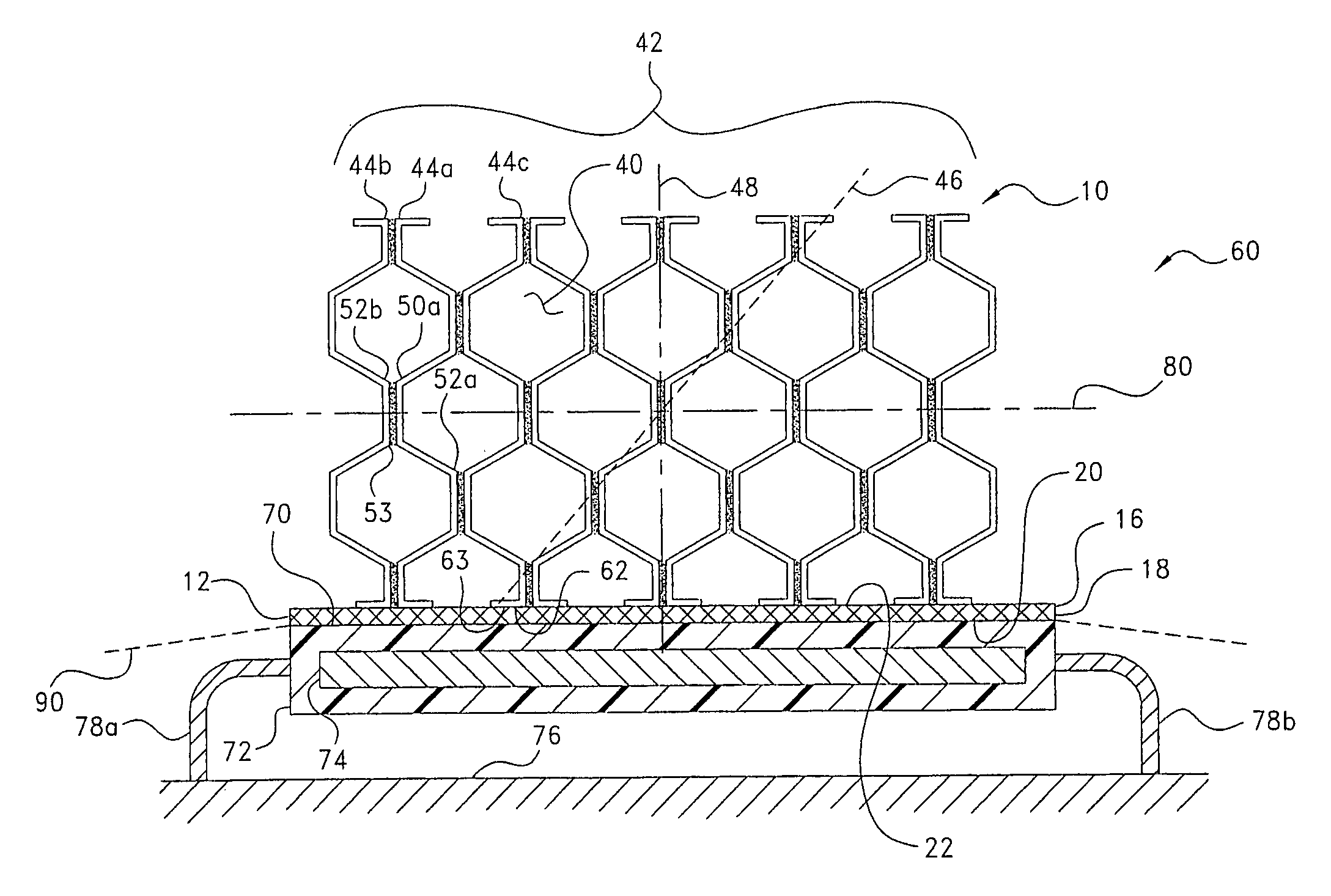
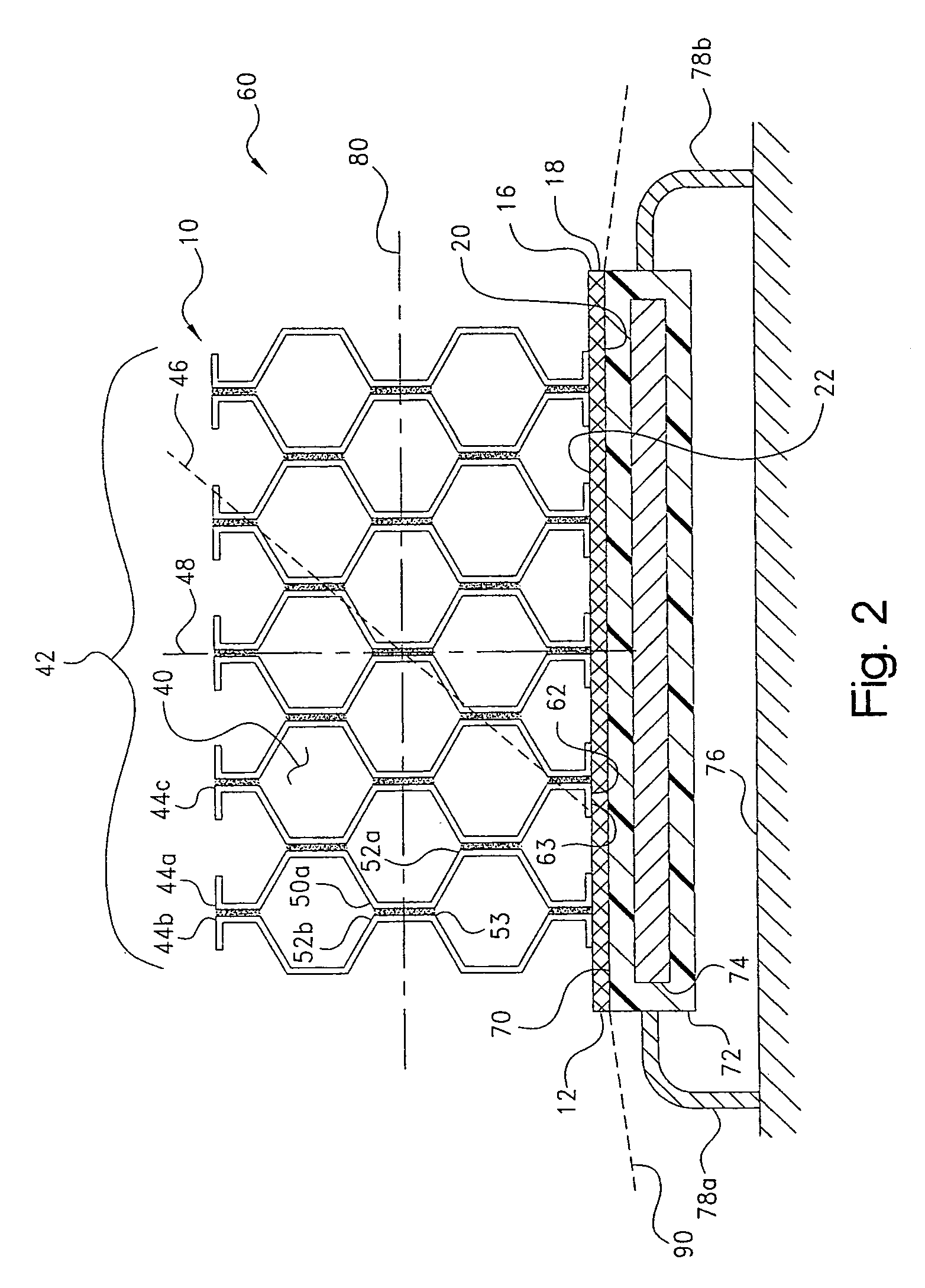
[0044]A representative heat sink according to the present invention was constructed for characterization. The sample was prepared by cutting a 0.66 inch (1.7 cm) thick sheet of aluminum foil honeycomb into a 1×1 inch (2.5×2.5 cm) square. An 11 mil (0.28 mm) thick layer of an doubled-sided thermal tape (Thermattach™ T411, silicone PSA supported on an expanded aluminum mesh, thermal impedance @2 / W (6.5° C.-cm2 / W), Parker Chomerics Division, Woburn, Mass.) was applied to one side of the square. The heat sink sample so constructed weighed about 1.9 g.

[0045]The heat sink sample was surface mounted under a hand-applied pressure to a TO-220 power supply run at 6 watts. The assembly were centered within a wind tunnel operated at 100 linear feet per minute (LFM) with the honeycomb openings in the heat sink aligned in the direction of air flow. At steady-state, typically after about 35 minutes, the case temperature of the power supply was recorded.

[0046]The experimental results, wherein all t...


PUM


Abstract

A heat sink disposable on a heat transfer surface of a heat-generating source such as an electronic component. The heat sink includes a base portion and a body portion. The base portion has a first surface disposable on the heat transfer surface, and a second surface opposite the first surface. The body portion is joined to the second surface of the base portion and is formed of a stack of corrugated sheets of one or more metal foils arranged to form a cellular, honeycomb-like structure.

Description

CROSS-REFERENCE TO RELATED CASES[0001]The present application claims the benefit of the filing date of U.S. Provisional Application Ser. No. 60 / 567,745; filed May 3, 2004, the disclosure of which is expressly incorporated herein by reference.BACKGROUND OF THE INVENTION[0002]The present invention relates broadly to thermal management devices for electronic components, such as integrated circuit (IC) chips. More particularly, the invention relates to a thermal dissipator, i.e., heat sink, for attachment to the heat transfer surface of an electronic component for the conductive and / or convective cooling of the component.[0003]Circuit designs for modem electronic devices such as televisions, radios, computers, medical instruments, business machines, communications equipment, and the like have become increasingly complex. For example, integrated circuits have been manufactured for these and other devices which contain the equivalent of hundreds of thousands of transistors. Although the c...

Claims


Application Information

Patent Timeline
Patent Type & Authority Patents(United States)
IPC IPC(8): F28F3/02H01L23/36H01L23/367H01L23/40H05K7/20
CPCH01L23/367H01L23/3672H01L23/467F28F3/02F28F3/025H01L2924/3011F28F2013/006H01L2924/0002H01L2924/00
Inventor MITCHELL, JONATHAN E.BUNYAN, MICHAEL H.
Owner PARKER INTANGIBLES LLC
Why Eureka
Try Eureka