Advanced endovascular graft

a technology of endovascular graft and graft body, which is applied in the field of advanced endovascular graft, can solve the problems of significantly increasing the likelihood of complications, high morbidity and mortality rate of open surgery, and significantly reducing recovery time, so as to reduce the potential for undesirable in-folding, enhance the stiffness of the graft body section, and less sensitive to in-folding

Inactive Publication Date: 2006-12-12
BOSTON SCI CORP
View PDF595 Cites 288 Cited by
  • Summary
  • Abstract
  • Description
  • Claims
  • Application Information

AI Technical Summary

Benefits of technology

[0025]When inflated, the serrated inflatable cuffs of the present invention are less sensitive to in-folding that can be caused by diametric interference of the graft with the body lumen. In some configurations, the serrated inflatable cuffs may comprise varying radii in the serrations to further reduce the potential for undesirable in-folding.
[0026]The graft body section may also include one or more inflatable channels. The channel or channels typically may be disposed between and in fluid communication with either or both proximal and distal inflatable cuffs. The channel or channels enhance the graft body section stiffness upon their inflation, help to prevent kinking of the graft body section, and may also facilitate deployment of the graft within a patient's body passageway. The inflatable channel or channels can be in a longitudinal and / or linear configuration with respect to the graft body section, but alternatively may take on a helical or circumferential configuration or some combination thereof. Other orientations such as interconnecting grids or rings may also be suitable alone or in combination with any of the other configurations.
[0027]The inflatable channels may also have a serrated pattern to provide kink resistance or folding resistance. The serrated inflatable channel may be disposed helically, circumferentially, in an annular rib and spine configuration, or the like. Kink resistance of such inflatable channels may be enhanced due to the ability of the serrations to hinge so as to prevent the formation of longitudinal folds. In some configurations, the serrations may have differing inner and outer radii.
[0028]The channels that connect the adjacent inflatable channels (either serrated or non-serrated circumferential rings) may alternatively have a staggered or discontinuous longitudinal channel or spine to promote flexibility of the graft body or limb.
[0029]The endovascular graft may have one or more inflatable longitudinal channels, or spines, and one or more circumferential inflatable channels, any of which may be designed to have the ability to shorten and lengthen to adjust for differences in the length and tortuousity of the patient's vessels or body lumens without unacceptable kinking. The longitudinal channel or spine may comprise one or more predetermined “kink spots” disposed, for example, between adjacent circumferential inflatable channels. The longitudinal channel may be configured to kink one or more times between each circumferential inflatable channel, thus reducing the amount of intrusion of each kink into the graft lumen.
[0030]The longitudinal channel or spine that interconnects the inflatable channels (and proximal and distal cuffs) may also take on a nonlinear or wave-type configuration so as to allow for improved compression in the graft longitudinal direction. Such a configuration may further reduce the potential for the graft to kink during foreshortening.

Problems solved by technology

Such cardiovascular indications often require intervention due to the severity of the sequelae, which frequently is death.
Despite its advantages, however, open surgery is fraught with high morbidity and mortality rates, primarily because of the invasive and complex nature of the procedure.
In addition, the typical patient in need of aneurysm repair is older and in poor health, facts that significantly increase the likelihood of complications.
Recovery times are significantly reduced as well, which concomitantly diminishes the length and expense of hospital stays.
These catheters also tend to have a high bending stiffness.
Such limitations result in the need for a surgical cut-down to deliver the stent-graft and make delivery through the often narrow and irregular arteries of diseased vessels difficult and risky.
Because of this, endovascular treatment of aortic aneurysmal disease is not available to many patients who could otherwise benefit from it.

Method used


Image

  • Advanced endovascular graft
  • Advanced endovascular graft
  • Advanced endovascular graft

Examples


Embodiment Construction

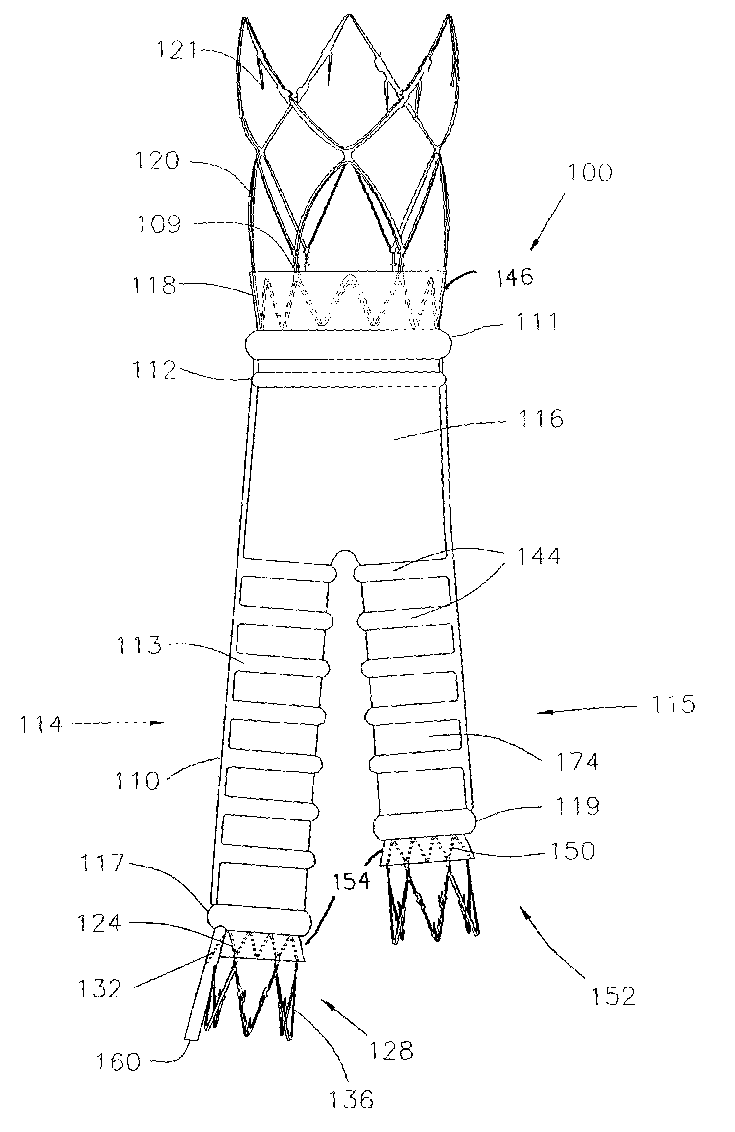
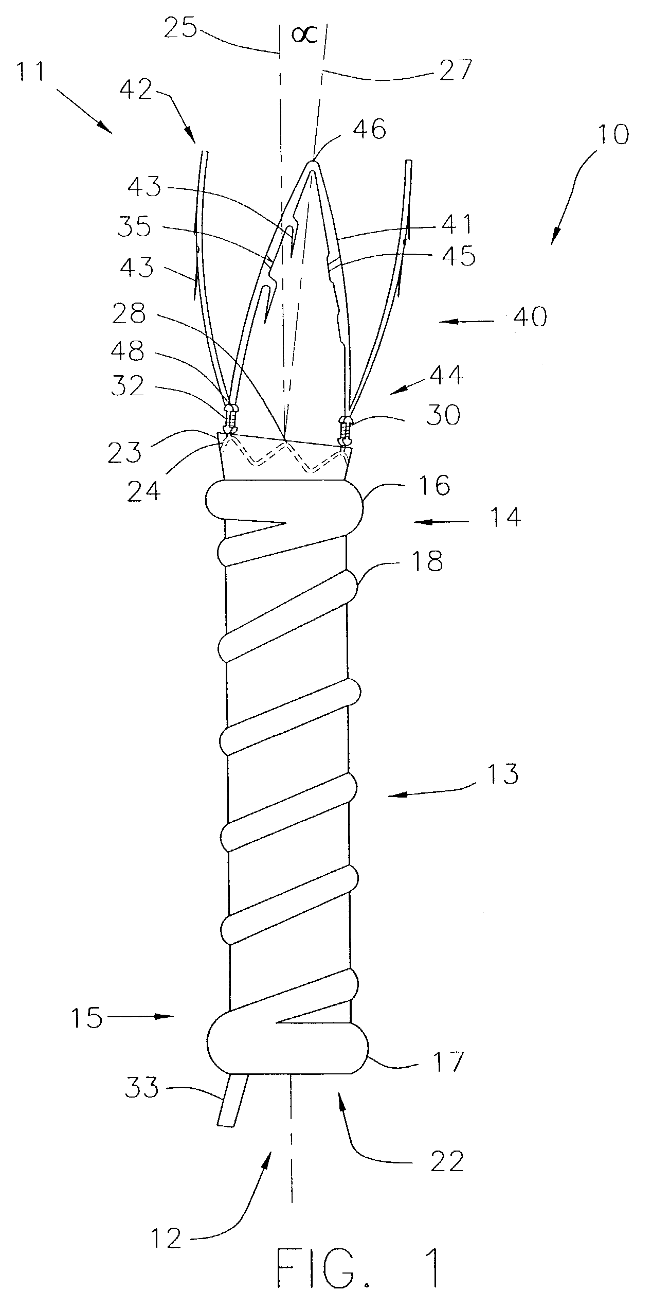
[0080]FIG. 1 shows an endovascular graft 10 in its deployed configuration. Unless otherwise stated, the term “graft” or “endovascular graft” is used herein to refer to a prosthesis capable of repairing and / or replacing diseased vessels or portions thereof, including generally tubular and bifurcated devices and any components attached or integral thereto. For. purposes of illustration, the graft embodiments described below are assumed to be most useful in the endovascular treatment of abdominal aortic aneurysms (AAA). For the purposes of this application, with reference to endovascular graft devices, the term “proximal” describes the end of the graft that will be oriented towards the oncoming flow of bodily fluid, typically blood, when the device is deployed within a body passageway. The term “distal” therefore describes the graft end opposite the proximal end. Finally, while the drawings in the various figures are accurate representations of the various embodiments of the present in...


PUM


Abstract

This invention is a system for the treatment of body passageways; in particular, vessels with vascular disease. The system includes an endovascular graft with a low-profile delivery configuration and a deployed configuration in which it conforms to the morphology of the vessel or body passageway to be treated as well as various connector members and stents. The graft is made from an inflatable graft body section and may be bifurcated. One or more inflatable cuffs may be disposed at either end of the graft body section. At least one inflatable channel is disposed between and in fluid communication with the inflatable cuffs.

Description

CROSS-REFERENCES TO RELATED APPLICATIONS[0001]This application is a continuation-in-part of U.S. patent application Ser. No. 10 / 091,641 entitled “Advanced Endovascular Graft,” filed on Mar. 5, 2002 by Chobotov et al., now abandoned which is a continuation of U.S. patent application Ser. No. 10 / 029,559 entitled “Advanced Endovascular Graft,” filed on Dec. 20, 2001 by Chobotov et al., the complete disclosures of which are incorporated herein by reference in their entirety.[0002]This application is also related to U.S. patent application Ser. No. 10 / 029,570 entitled “Method and Apparatus for Shape Forming Endovascular Graft Material” by Chobotov et al., U.S. patent application Ser. No. 10 / 029,584 entitled “Endovascular Graft Joint and Method for Manufacture” by Chobotov et al., U.S. patent application Ser. No. 10 / 029,557 entitled “Method and Apparatus for Manufacturing an Endovascular Graft Section”, by Chobotov et al. All of the above applications are commonly owned and were filed on ...

Claims


Application Information

Patent Timeline
Patent Type & Authority Patents(United States)
IPC IPC(8): A61F2/06A61F2/86A61B17/00A61F2/00A61F2/02A61F2/07
CPCA61F2/07A61F2/962A61F2002/065A61F2002/075A61F2002/8486A61F2250/0003A61F2250/0036A61F2/89A61F2/954A61M2025/0177A61F2002/9511A61F2002/9517A61F2002/9505A61F2/915A61F2/9517
Inventor CHOBOTOV, MICHAEL V.GLYNN, BRIAN A.KARI, STUART E.MARTHALER, JOHN M.WHIRLEY, ROBERT G.ZACHARIAS, ISAAC J.STEPHENS, W. PATRICK
Owner BOSTON SCI CORP
Why Eureka
Try Eureka