Apparatus for measuring electrical impedance

a technology for measuring apparatuses and electrical impedances, applied in the field of apparatuses for measuring electrical impedances correctly, can solve the problems of high frequency, difficult to measure body impedance correctly at high frequency, and occur in the measurement of electrical impedances, etc., and achieve the effect of reducing errors

Inactive Publication Date: 2006-12-12
INFORMATION & COMM UNIV RES & INDAL COOPERATION GROUP +1
View PDF13 Cites 35 Cited by
  • Summary
  • Abstract
  • Description
  • Claims
  • Application Information

AI Technical Summary

Benefits of technology

[0016]The contribution of the present invention is to provide an apparatus for measuring electrical impedance for reducing errors caused by a common mode voltage and by an insufficient impedance of a preamplifier, thus measuring electrical impedance correctly.

Problems solved by technology

However, various errors can occur at high frequency in an apparatus for measuring electrical impedance.
Particularly, it is not easy to measure body impedance correctly at high frequency.
One of the representative errors occurring in measurement of the electrical impedance is due to a common mode voltage inputted to a difference amplifier.
Another error is due to a limited input impedance of a preamplifier.
However, the two errors increase as frequency rises.
In case that common mode voltage is high, a voltage outputted from a difference amplifier is incorrect.
However, a conventional common mode feedback method has a problem of oscillation at a high frequency.
Therefore, it is difficult to apply a common mode feedback method at a high frequency over tens of kHz.
Thus, a loading error occurs, since input impedance of the preamplifier is not high enough compared to that of an electrode.
However, as a frequency gets high, a loop gain becomes high, which causes a risk of oscillation.
Therefore, an operational amplifier of narrow bandwidth should be used to suppress oscillation in the conventional method, making it difficult to select an operational amplifier with adequate bandwidth considering impedance of electrode.
Further, it is difficult to change a gain margin when impedance of electrode is changed.
And if a preamplifier has gain peaking generated at a frequency of maximum loop gain, the gain margin corresponding to gain peaking vanishes, which results in easy oscillation.
In sum, an apparatus for measuring electrical impedance causes an error by a common mode voltage and another error by an insufficient impedance of a preamplifier.

Method used


Image

  • Apparatus for measuring electrical impedance
  • Apparatus for measuring electrical impedance
  • Apparatus for measuring electrical impedance

Examples


Embodiment Construction

[0024]Hereinafter, preferred exemplary embodiment is explained referring to the drawings in detail.

[0025]While this invention has been described in connection with what is presently considered to be the most practical and preferred embodiment, it is to be understood that the invention is not limited to the disclosed embodiments, but, on the contrary, is intended to cover various modifications and equivalent arrangements included within the spirit and scope of the appended claims.

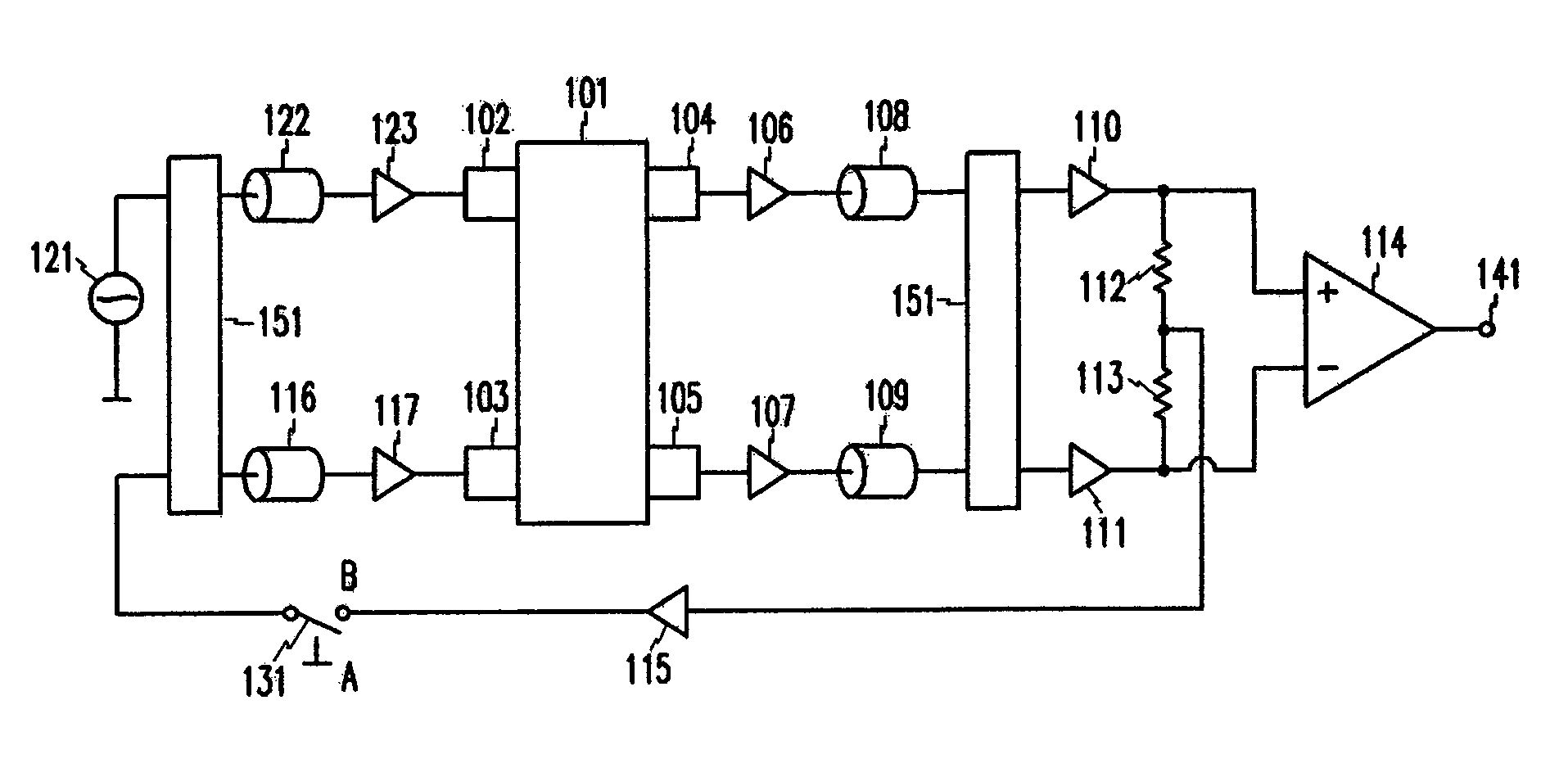
[0026]FIG. 1 shows an apparatus for measuring electrical impedance according to the exemplary embodiment of the present invention. In FIG. 1, when a switch is connected to A, a very high common mode voltage occurs since a common mode feedback is not performed. In case the switch is connected to B, the common mode feedback signal of the present invention is applied. In FIG. 1, for convenience, a voltage source 121 is applied instead of a current source usually used in the conventional method, in order to appl...


PUM


Abstract

The present invention provides an apparatus for measuring electrical impedance comprising: two input electrodes contacted to a subject for measuring impedance; a difference amplifier to which two signals inputted to the two input electrodes are inputted; a device for extracting a common mode component of two signals inputted to the two input electrodes; the third electrode contacted to the subject for measuring impedance; the first multiplier to which the common mode component is inputted; the first filter coupled with the first multiplier; the second multiplier coupled with the first filter; wherein a feedback signal outputted from the second multiplier is inputted to the third electrode.

Description

CROSS REFERENCE TO RELATED APPLICATION[0001]This application claims priority to and the benefit of Korea Patent Application No. 10-2004-0001159 filed on Jan. 8, 2004 in the Korean Intellectual Property Office, the entire content of which is incorporated herein by reference.BACKGROUND OF THE INVENTION[0002](a) Field of the Invention[0003]The present invention relates to an apparatus for measuring electrical impedance correctly. More specifically, the present invention relates to an apparatus for measuring electrical impedance applicable for a reliable analysis of body fat. However, the apparatus according to the present invention can be applied to other fields apart from analysis of body fat.[0004]The apparatus for measuring electrical impedance includes a device applying electrical current to a subject and a difference amplifier measuring difference voltage induced to the subject. The apparatus for measuring electrical impedance can be applied in various fields. For example, body fa...

Claims


Application Information

Patent Timeline
Patent Type & Authority Patents(United States)
IPC IPC(8): G01R27/04A61B5/05G01R27/02
CPCG01R27/02E02B13/00
Inventor PARK, SIN-CHONGHWANG, IN-DUK
Owner INFORMATION & COMM UNIV RES & INDAL COOPERATION GROUP
Why Eureka
Try Eureka