
Device for positional and/or length determination

a technology of position and/or length, applied in the direction of speed measurement using gyroscopic effects, magnetic field controlled resistors, transmission systems, etc., can solve the problems of potential difficulty in guiding and controlling, bulky sensor heads that cooperate with the magnetic length coding, and inhomogeneous magnetization. , to achieve the effect of reliable position determination, short processing time and simple manner

Inactive Publication Date: 2006-12-12
ELGO ELECTRONICS GMBH & CO KG
View PDF20 Cites 10 Cited by
  • Summary
  • Abstract
  • Description
  • Claims
  • Application Information

AI Technical Summary

Benefits of technology

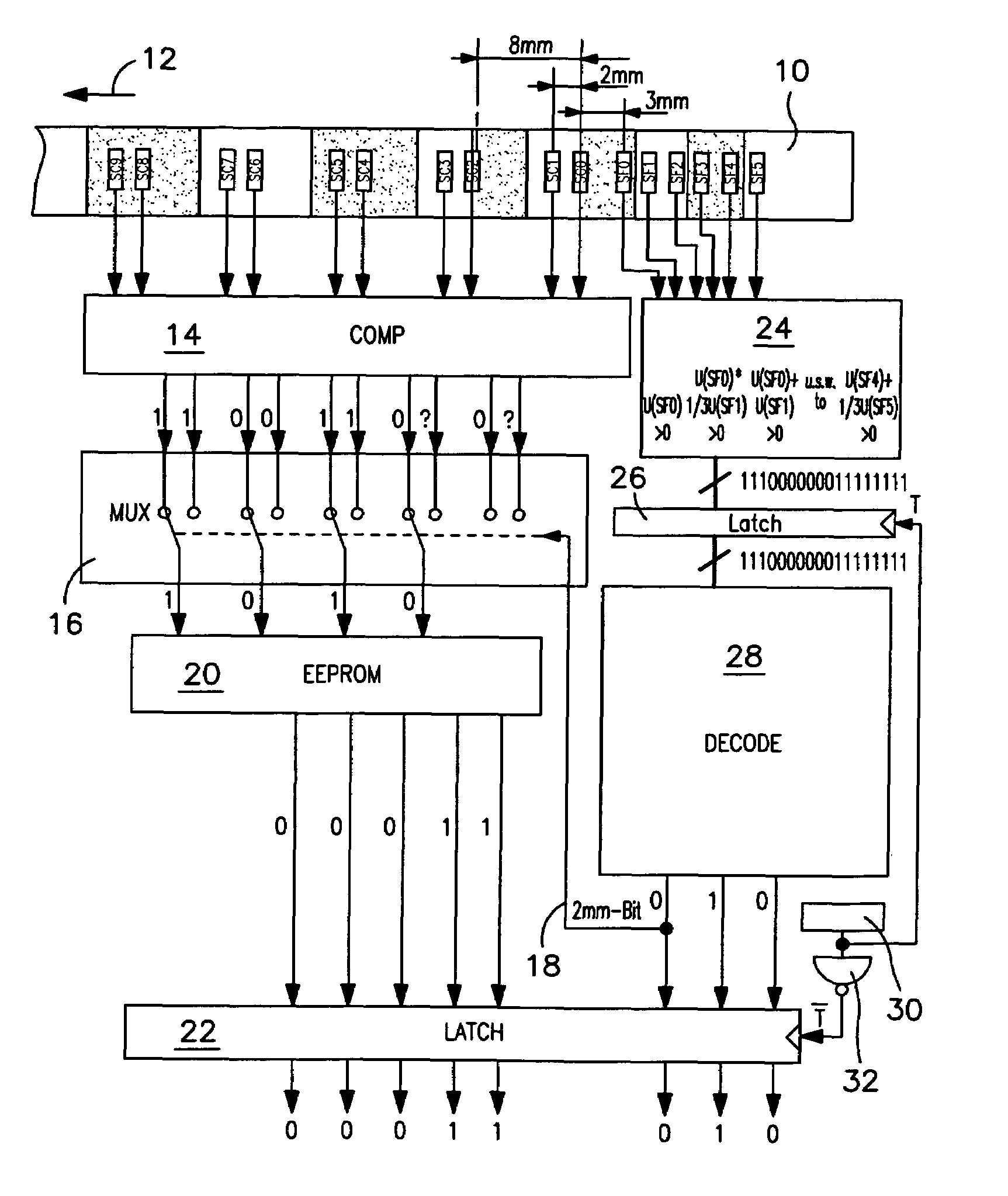
"The invention is a device that uses a carrier unit with a length coding and a measuring unit that can move relative to the carrier unit. The carrier unit is elongate and rod-shaped, and has a plurality of coding sections with a regular pole division. The coding sections have a maximum of two coding sections of the same polarity that are adjacent to each other. The device also includes selection means for the magnetic sensor units and interpolation sensors for precise position determination within a coding section or pole division. The invention combines the advantages of absolute one-track systems (slim carrier unit and compact sensor head) with the high resolution of systems having two or more tracks."

Problems solved by technology

However, such devices which are known from the prior art and are considered to be generic have the disadvantage that, in order to achieve an absolute magnetic length coding, typically at least two parallel tracks of the length coding have to be provided in order to form a useful length resolution for the desired absolute coding.
As a result, however, on the one hand the carrier unit is problematic to produce (and in particular is still not very suitable for curved carrier units provided with the length coding), and also the sensor head that cooperates with the magnetic length coding is bulky and difficult to handle and is thus potentially difficult to guide and control.
A further disadvantage of absolute codings, particularly those which are generated by means of a so-called random code or pseudo-random code, is that, on account of a relatively asymmetric distribution of coding sections magnetized with the respective polarity, magnetization inhomogeneities may occur, particularly with regard to a so-called intersymbol interference (the magnetic signal of smaller poles is impaired by adjacent large areas, that is to say a number of areas having identical poles) .
This in turn adversely affects the reading reliability of the carrier unit.

Method used


Image

  • Device for positional and/or length determination
  • Device for positional and/or length determination
  • Device for positional and/or length determination

Examples


Embodiment Construction

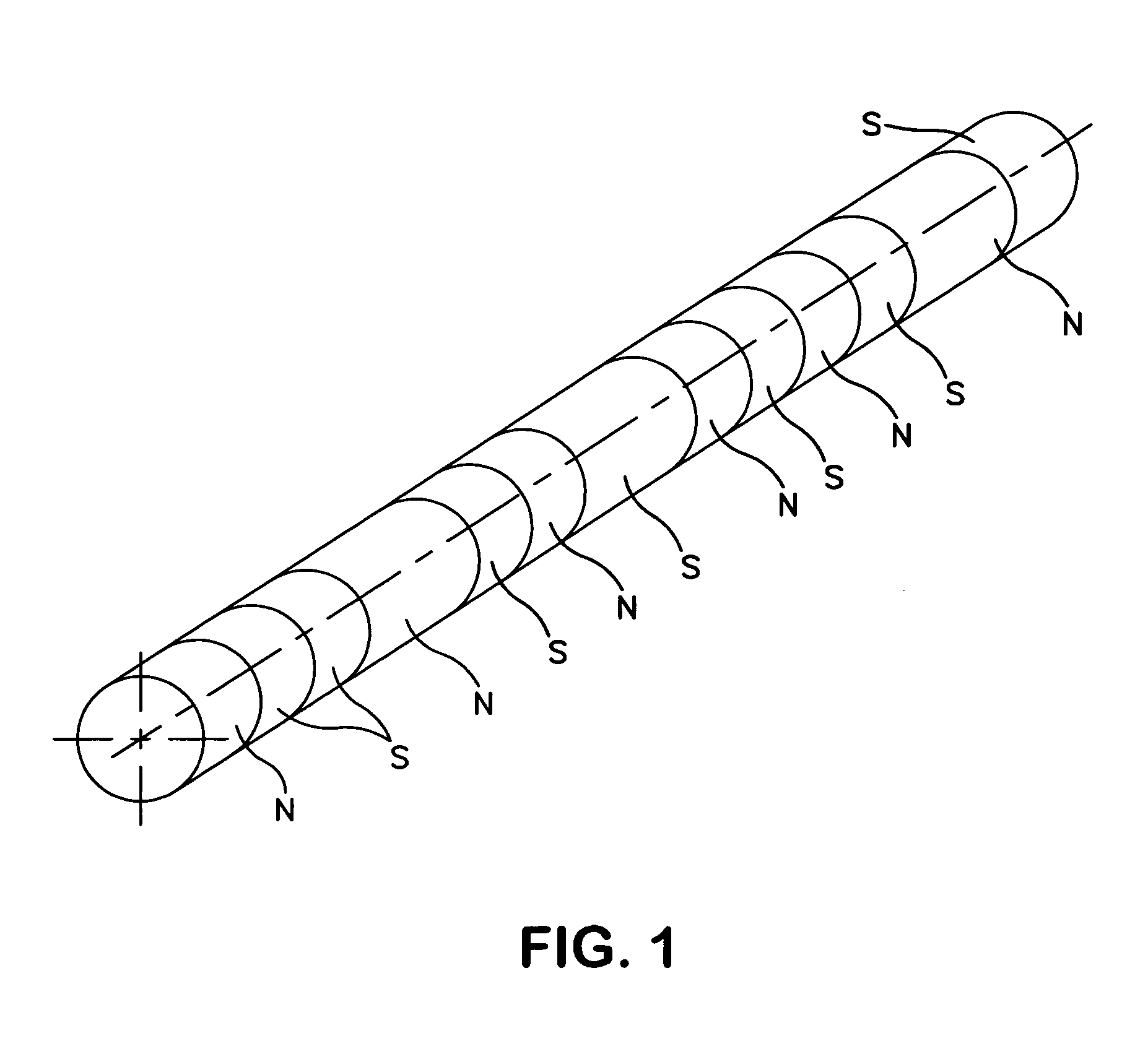
[0031]The carrier unit shown by way of example in FIG. 1, for instance the region of a piston rod or the like, according to the invention has a coding in the form of a combination of pseudo-random sequence and Manchester coding. Specifically, the radially magnetized length coding (along the longitudinal direction “X”) which is used in FIG. 1 is formed such that, with an exemplary pole division p=4 mm, an n-bit pseudo-random sequence is generated as digital signal, which codes 2n−1 different position values; this value multiplied by the pole division (in this case 4 mm) then gives the maximum coding length.

[0032]Based on this sequence, a magnetization of value “1” is then inserted behind each magnetization “0” (for the sake of simplification the signals corresponding to polarities N and S will be referred to below in binary terms as “1” and “0”, respectively), and a magnetization of value “0” is inserted behind each magnetization of value “1”; the magnetization of the carrier unit th...


PUM


Abstract

A device for positional and / or length determination comprising a carrier unit with an absolute magnetic length coding and a measuring unit that co-operates with the carrier measuring unit and can be displaced in relation to the latter. The measuring unit has a magnetic sensor unit (Sci, Sfi) and can be connected to an electronic evaluation unit (18 to 32) that is located downstream of the measuring unit. The elongated, rod-shaped carrier unit (10) is provided with one track of preferably radially magnetized length coding, a plurality of coding sections comprising periodic pole divisions is provided along the length coding and coding sections of a first polarity alternate with coding sections of a second polarity along the carrier unit, in such a way that a maximum of two coding sections of the same polarity lie directly adjacent to one another.

Description

BACKGROUND OF THE INVENTION[0001]The present invention relates to a device for position and / or length determination.[0002]Such devices are used in particular in an industrial context for length measurement, for instance typically in connection with ascertaining movements of or lengths traveled by a machine tool or in corresponding measurement tasks in a materials-handling or conveying system.[0003]Such length measurement systems typically have a carrier unit which is provided with a magnetic length coding. Such a length measurement device is known, for example, from the German utility model 200 12 703 by the Applicant.[0004]Also known from the prior art are devices which have an absolute magnetic coding, and by way of example reference should be made to German patent application 197 32 713 by the Applicant.[0005]Compared to relatively coded systems, such absolute codings have the advantage that end or reference positions do not have to be detected; rather, the position along the car...

Claims


Application Information

Patent Timeline
Patent Type & Authority Patents(United States)
IPC IPC(8): H03M1/22G01B7/14G01R33/09G01D5/249
CPCG01D5/2495G01D5/2497
Inventor MULLER, FRANK
Owner ELGO ELECTRONICS GMBH & CO KG
Learn More