
Subcutaneous cardiac stimulator device having an anteriorly positioned electrode

a cardiac stimulator and electrode technology, applied in the direction of electrotherapy, heart defibrillators, therapy, etc., can solve the problems of abnormal performance of the av node, loss of blood flow to the rest of the body, stimuli generated by the heart's own natural pacemaker, etc., to achieve the effect of reducing the degree of surgical intervention

Inactive Publication Date: 2006-12-12
CAMERON HEALTH
View PDF82 Cites 275 Cited by
  • Summary
  • Abstract
  • Description
  • Claims
  • Application Information

AI Technical Summary

Benefits of technology

[0017]One embodiment of the present invention provides a subcutaneous cardiac stimulator device adapted to generate an electric field across the heart using at least one subcutaneous electrode positioned at a location selected to minimize the degree of surgical intervention.

Problems solved by technology

Bradycardia often results from abnormal performance of the AV node.
During a bradycardial event, stimuli generated by the heart's own natural pacemaker, the SA node, are improperly conducted to the rest of the heart's conduction system.
Tachycardia often results from isehemic heart disease in which local myocardium performance is compromised and coordinated contraction of heart tissue is lost which leads to a loss of blood flow to the rest of the body.
This system is very complicated and it is difficult to implant surgically.
However, commercially available ICDs have several disadvantages.
First, commercially available ICDs must be implanted using somewhat complex and expensive surgical procedures that are performed by specially trained physicians.
These rooms are limited in number and therefore, limit the number of lead placement procedures, and ultimately the number of ICDs, that may be implanted in any given day.
Second, commercially available ICDs rely on transvenous leads for the placement of at least one electrode within the cardiac chambers.
It has been found that over a period of time, transvenous lead electrodes may get dislodged from the cardiac tissues.
Additionally, complications such as broken leads and undesirable tissue formations deposits on the electrodes are not uncommon.
These problems are especially acute when leads carry two or more electrodes.
Moreover, infection is a concern when implanting leads within a patient's vasculature.
Third, removing these ICDs and replacing them, if necessary, also requires complicated surgical procedures that may be more life-threatening than the initial implantation.

Method used


Image

  • Subcutaneous cardiac stimulator device having an anteriorly positioned electrode
  • Subcutaneous cardiac stimulator device having an anteriorly positioned electrode
  • Subcutaneous cardiac stimulator device having an anteriorly positioned electrode

Examples


Embodiment Construction

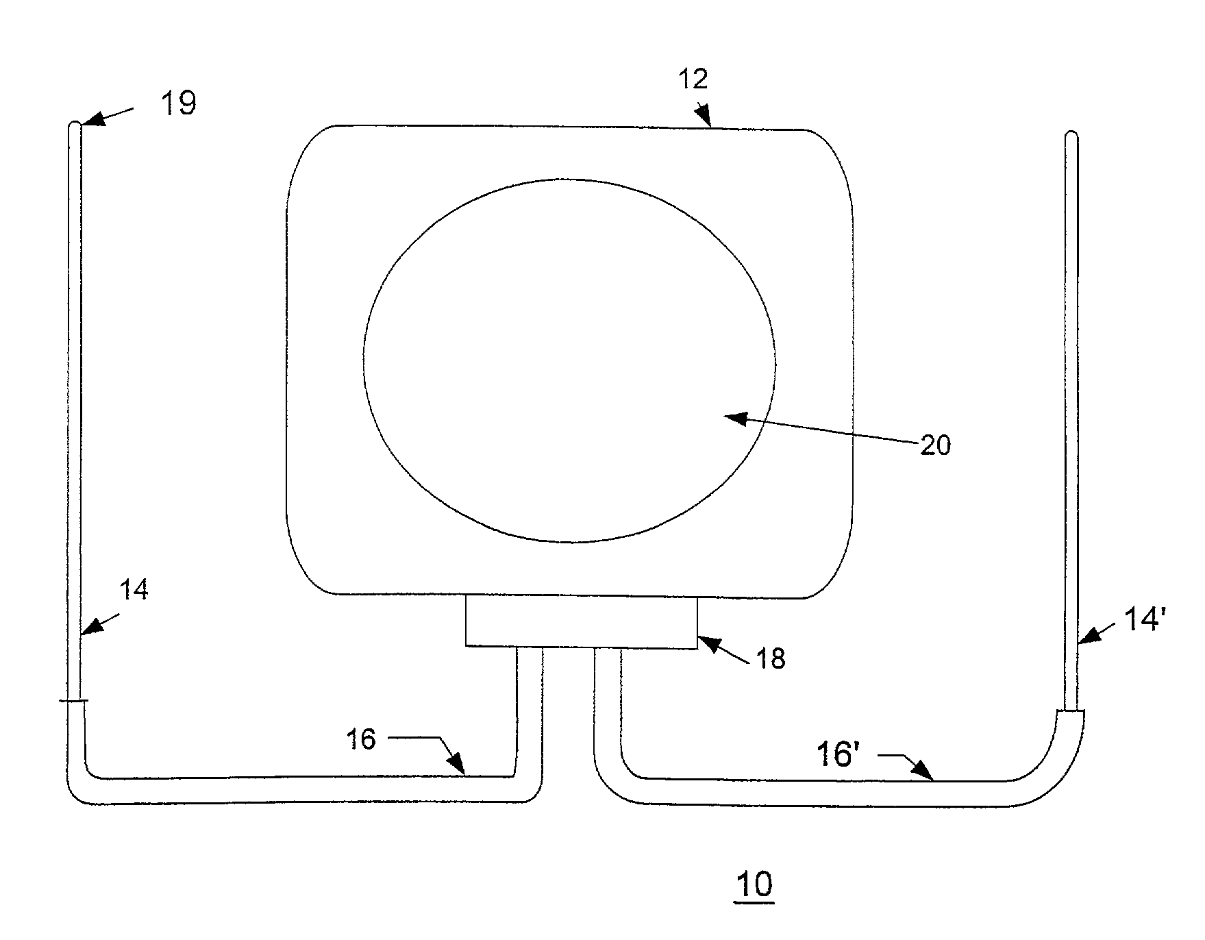
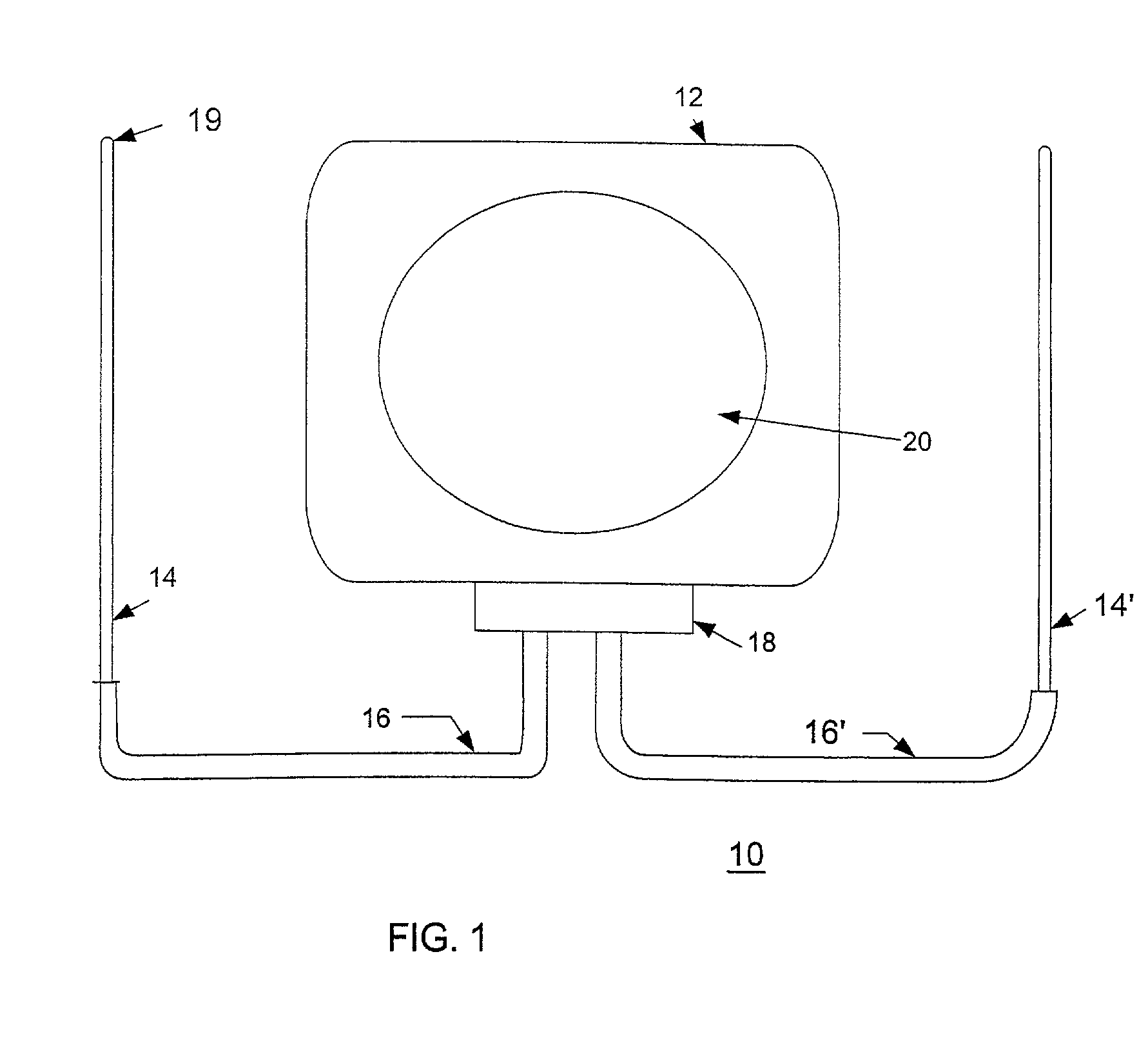
[0044]Referring now to the drawings, FIG. 1 shows an implantable cardiac device 10 constructed in accordance with one embodiment of the present invention. The device 10 includes a housing 12 containing a pulse generator (not shown), an electrode 14 and a lead 16. The electrode 14 is connected to the pulse generator through a header 18 disposed on the housing 12.

[0045]In particular embodiments of the present invention, the housing 12 can act as an active housing. In this embodiment, the housing 12 itself, comprises a second electrode for the ICD device 10. An active canister housing 12 is formed either with a continuously conductive surface, or with a separate conductive zone 20. The conductive surface or zone 20 of an active canister housing 12 is connected electrically to the circuitry disposed in the housing 12. If the whole housing 12 is used as an active electrode, then its surface area presents a low interface resistance with the patient's tissues, thereby lowering the losses i...


PUM


Abstract

A subcutaneous cardiac device includes a subcutaneous electrode and a housing coupled to the subcutaneous electrode by a lead with a lead wire. The subcutaneous electrode is adapted to be implanted in a frontal region of the patient so as to overlap a portion of the patient's heart.

Description

RELATED APPLICATIONS[0001]This application is a continuation-in-part of application Ser. No. 10 / 011,956, filed Nov. 5, 2001, which is a continuation-in-part of application Ser. No. 09 / 940,599, filed Aug. 27, 2001, now U.S. Pat. No. 6,950,705, which is a continuation-in-part of application Ser. No. 09 / 663,607, filed Sep. 18, 2000, now U.S. Pat. No. 6,721,597, and application Ser. No. 09 / 663,606, filed Sep. 18, 2000, now U.S. Pat. No. 6,647,292.FIELD OF THE INVENTION[0002]The present invention relates to a device and method for performing electrical cardiac stimulation, including: cardioversion, defibrillation and, optionally, pacing of the heart using subcutaneous electrodes. More specifically, the present invention relates to implantable cardioverter-defibrillator having at least one subcutaneous electrode, wherein the electrode is positioned generally in the frontal portion of the thorax, thereby creating a substantially uniform electric field across a patient's heart.BACKGROUND OF...

Claims


Application Information

Patent Timeline
Patent Type & Authority Patents(United States)
IPC IPC(8): A61N1/372A61N1/375A61N1/39
CPCA61N1/375A61N1/3918A61N1/3956A61N1/3968A61N1/3756A61N1/3906A61N1/3975A61N1/37512
Inventor OSTROFF, ALAN H.ERLINGER, PAULBARDY, GUST H.
Owner CAMERON HEALTH
Learn More