Liquid fuel injection

a technology of liquid fuel injection and fuel line, which is applied in the direction of water supply installation, machines/engines, lighting and heating apparatus, etc., can solve the problems of fuel line blockage, fuel delivery system can become unusable, and solid carbon particles can be produced that block the fuel lin

Inactive Publication Date: 2006-12-19
KERR MCGEE CHEM CORP
View PDF16 Cites 13 Cited by
  • Summary
  • Abstract
  • Description
  • Claims
  • Application Information

AI Technical Summary

Benefits of technology

[0002]The chloride method for producing titanium dioxide (“TiO2”) consists of reacting preheated oxygen gas with titanium tetrachloride (“TiCl4”) gas to produce TiO2 particles. Additives in small amounts can be used to control the particle size and structure. Hydrocarbon fuel can be added to the preheated oxygen to increase its temperature further to a final oxygen temperature of about 3000° F. to about 3800° F. prior to the reaction with titanium tetrachloride vapor. The use of supplemental hydrocarbon fuel eliminates the need to build a hot oxygen supply system that can withstand the elevated temperatures that are required.
[0003]Hydrocarbon fuels either in the vapor phase or in the liquid phase can be used to increase the oxygen temperature to its final temperature during the TiO2 production process. There exist advantages to using hydrocarbon fuels in the liquid phase. These advantages include, for example, a safer means to deliver the fuel to the reaction zone, the use of low-grade, less costly fuel, and the ability to deliver additives to the reaction zone in a consistent manner by dissolving the additives in the fuel.
[0005]The present invention provides for liquid fuel injectors that allow the injection of a fine spray of liquid fuel. Liquid fuel injectors of the present invention utilize a schrader valve movable between an open position and a closed position. When the schrader valve is in the closed position fuel flow is blocked and purge gas is allowed to flow through the fuel injectors. When the schrader valve is in the open position, the flow of purge gas is blocked and fuel is allowed to flow through the fuel injector. In this manner, the fuel injectors of the present invention provide for an immediate and automatic purge of the fuel lines when the fuel flow is shut off.

Problems solved by technology

However, problems often arise when using liquid fuel injection systems in the production of TiO2.
If the fuel pyrolyzes, solid carbon particles can be produced that block the fuel lines and the fuel delivery system can become unusable.

Method used


Image

  • Liquid fuel injection
  • Liquid fuel injection
  • Liquid fuel injection

Examples


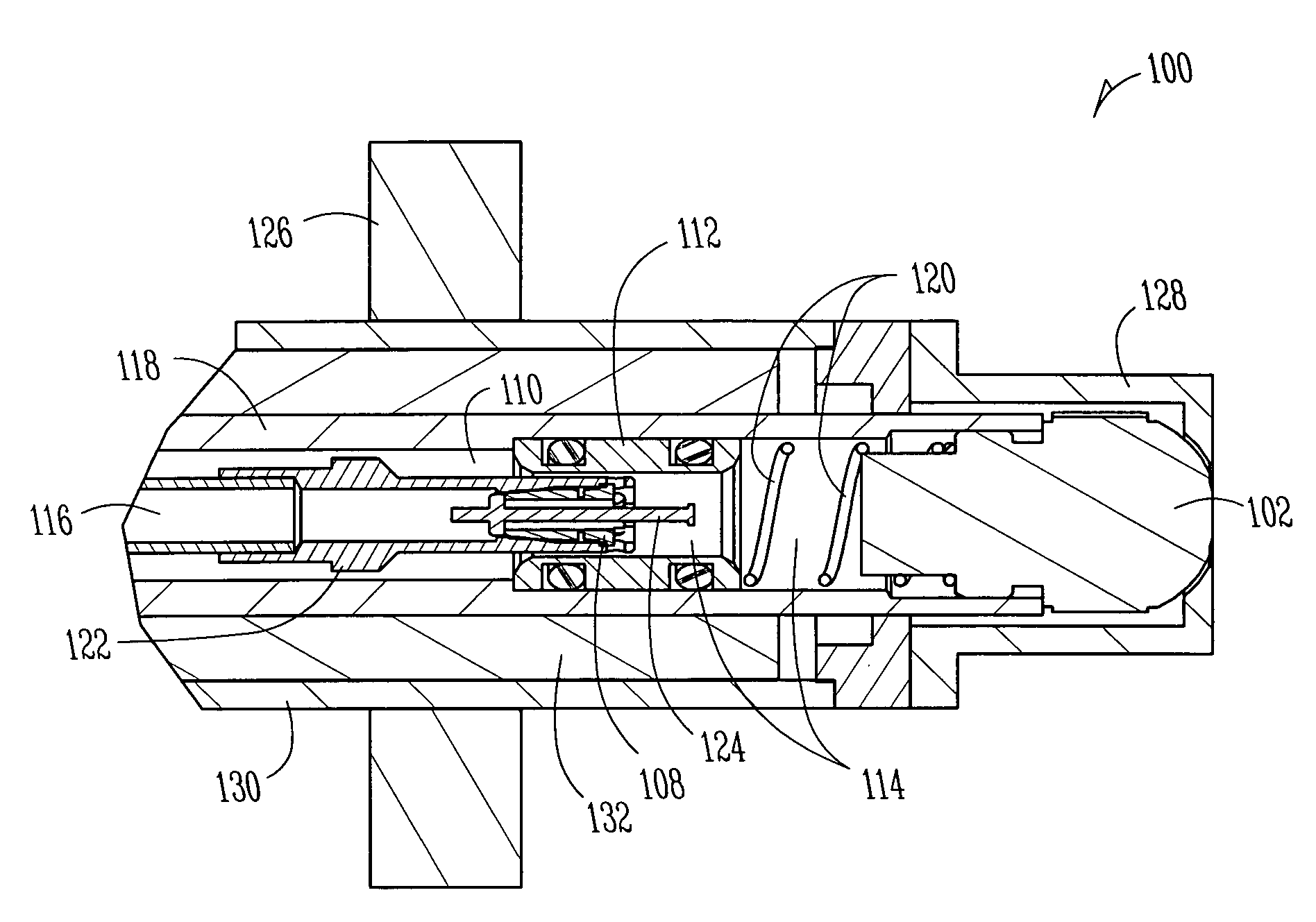
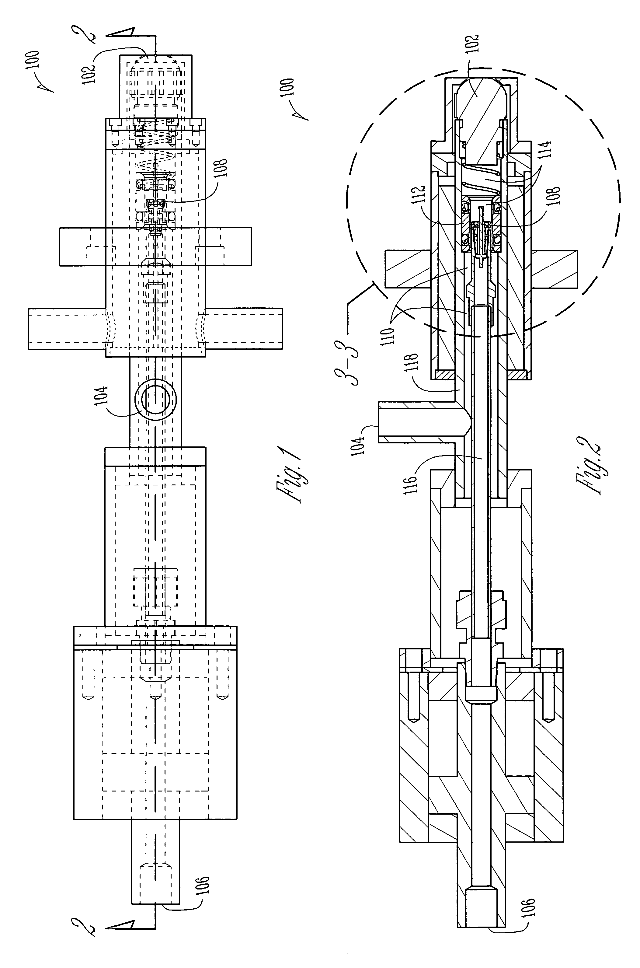
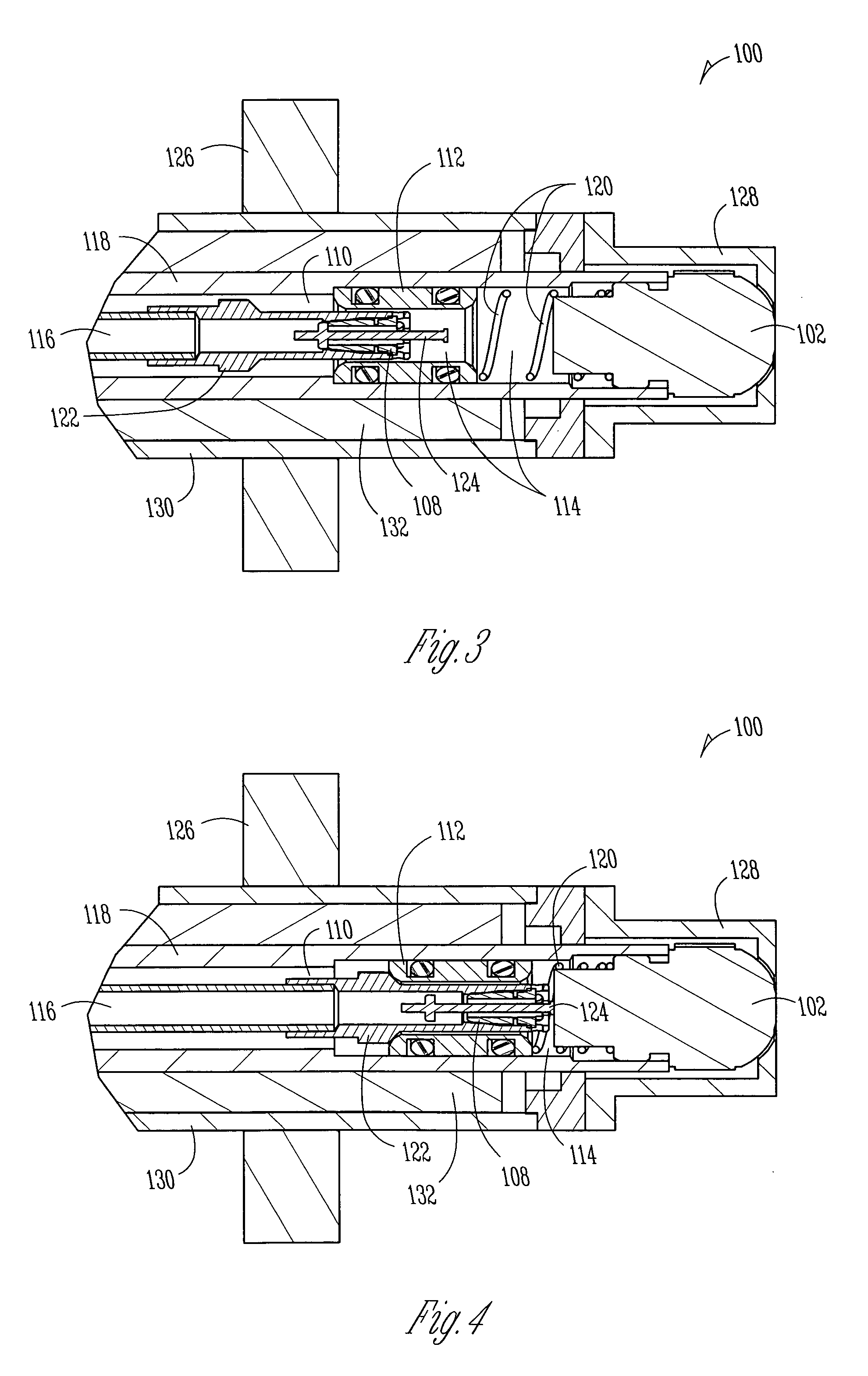
Embodiment Construction

[0012]In the following detailed description of preferred embodiments of the present invention, reference is made to the accompanying Drawings, which form a part hereof, and in which are shown by way of illustration specific embodiments in which the present invention may be practiced. It should be understood that other embodiments may be utilized and changes may be made without departing from the scope of the present invention.

[0013]Fuel injectors of the present invention comprise a nozzle; a purge gas inlet; a liquid fuel inlet; and a schrader valve, movable between an open position and a closed position, wherein the liquid fuel inlet is in communication with the nozzle when the schrader valve is in the open position and the purge gas inlet is not in communication with the nozzle when the schrader valve is in the open position, and wherein the liquid fuel inlet is not in communication with the nozzle when the schrader valve is in the closed position and the purge gas inlet is in com...


PUM


Abstract

Liquid fuel injectors are provided. The liquid fuel injectors allow the injection of a fine spray of liquid fuel. The liquid fuel injectors utilize a schrader valve movable between an open position and a closed position. When the schrader valve is in the closed position fuel flow is blocked and purge gas is allowed to flow through the fuel injectors. When the schrader valve is in the open position, the flow of purge gas is blocked and fuel is allowed to flow through the fuel injector. In this manner, the fuel injectors provide for an immediate and automatic purge of the fuel lines when the fuel flow is shut off.

Description

FIELD OF THE INVENTION [0001]The present invention generally relates to fuel injection technology. More specifically, the present invention relates to improved liquid fuel injection technology that can be advantageously utilized to inject hydrocarbon fuels into hot gases.BACKGROUND AND SUMMARY OF THE INVENTION [0002]The chloride method for producing titanium dioxide (“TiO2”) consists of reacting preheated oxygen gas with titanium tetrachloride (“TiCl4”) gas to produce TiO2 particles. Additives in small amounts can be used to control the particle size and structure. Hydrocarbon fuel can be added to the preheated oxygen to increase its temperature further to a final oxygen temperature of about 3000° F. to about 3800° F. prior to the reaction with titanium tetrachloride vapor. The use of supplemental hydrocarbon fuel eliminates the need to build a hot oxygen supply system that can withstand the elevated temperatures that are required.[0003]Hydrocarbon fuels either in the vapor phase or...

Claims


Application Information

Patent Timeline
Patent Type & Authority Patents(United States)
IPC IPC(8): F02M59/00F02C7/232F23D11/24F23D11/38F23K5/18
CPCF23D11/24F23D11/386F23D2209/30Y10T137/4259Y10T137/87684
Inventor MARTIN, ROBERT O.FLYNN, HARRY EUGENENATALIE, CHARLES A.
Owner KERR MCGEE CHEM CORP
Why Eureka
Try Eureka