Machining station

a technology of machining station and machining axis, which is applied in the direction of metal-working holders, supporters, positioning apparatuses, etc., can solve the problems of large construction volume of the two linear axes and the one rotational axis of the workpiece, large drive volume, and high cost, and achieve the effect of favourable production cost of the machining station

Active Publication Date: 2006-12-19
GROB WERKE & K G
View PDF16 Cites 30 Cited by
  • Summary
  • Abstract
  • Description
  • Claims
  • Application Information

AI Technical Summary

Benefits of technology

[0009]The present invention has the object to design known machining stations in a simpler way. By means of a simple des

Problems solved by technology

A few machining steps are carried out by the machining station, however, the plurality of the machining stations, one arranged behind the other, allow a varied and also complex machining of the workpiece.
It is a disadvantage in this state of the art that the construction for the two linear axes and the one rotational axis of the workpiece is very large.
The two linear axes in Y- and Z-direction are designed as compound rests and need, for a sufficientl

Method used


Image

  • Machining station
  • Machining station
  • Machining station

Examples


Embodiment Construction

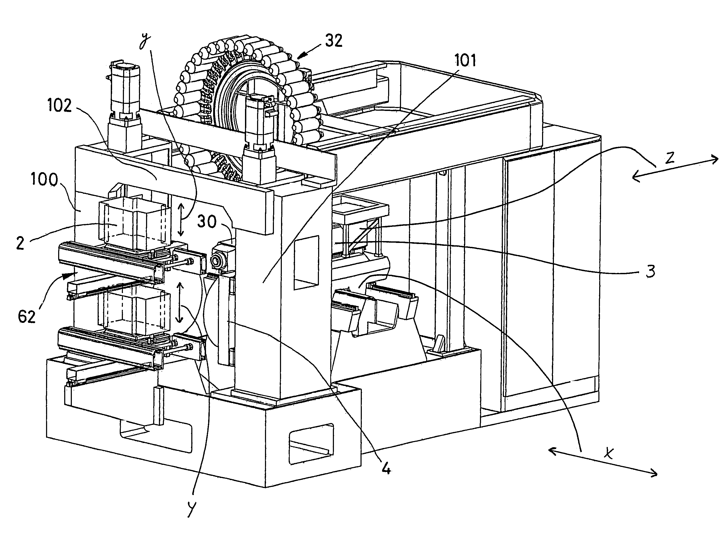
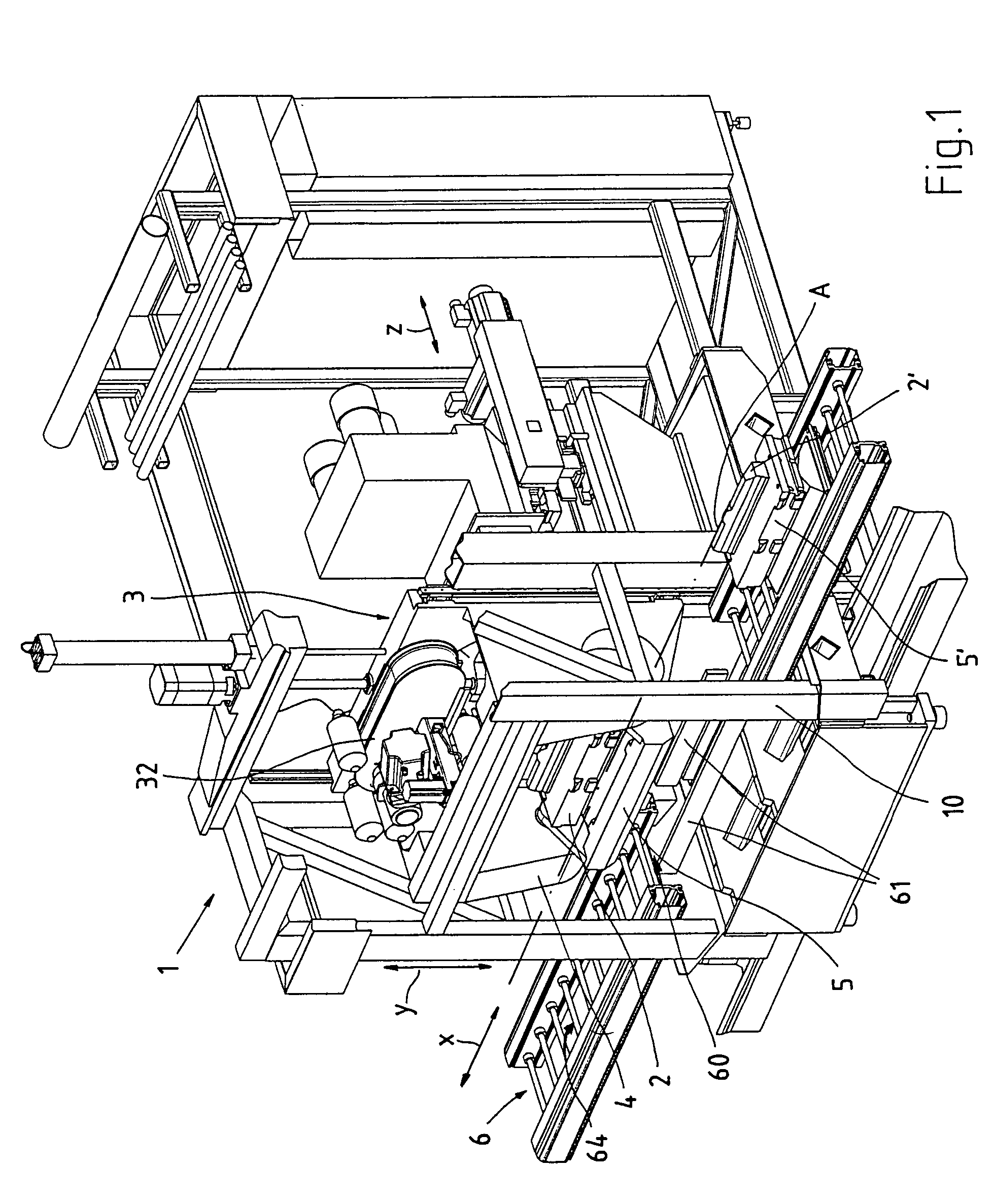
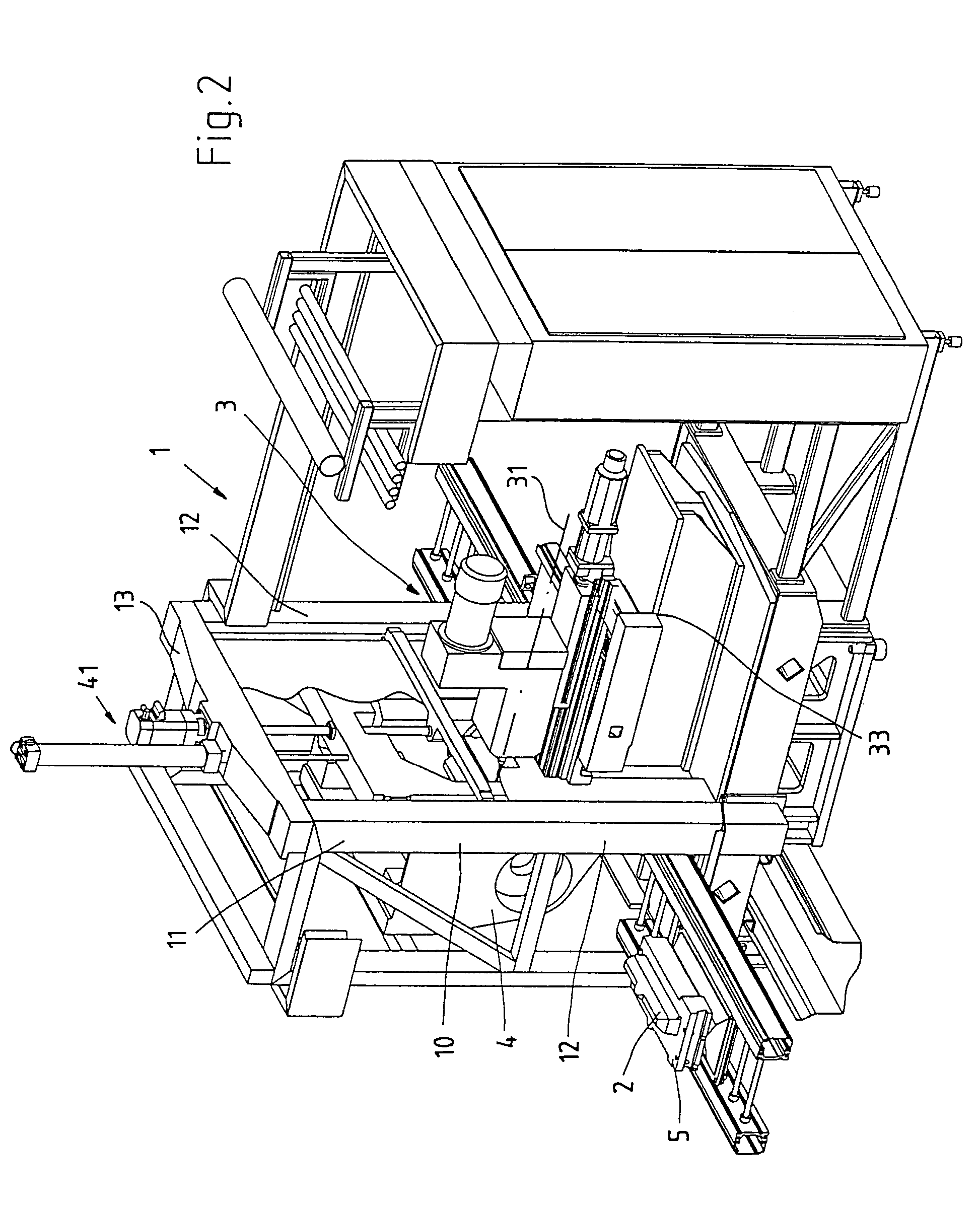
[0103]The machining station 1 according to the invention is shown, for example, in FIG. 1. It comprises essentially the machining unit 3 which serves for machining workpieces 2. The machining unit 3 can move along the Z-axis, which is parallel to the spindle axis, and can, if necessary, also move rectangular to that in the X-axis. Z- and X-axis are here horizontally, respectively essentially horizontally, orientated. The vertical axis (Y-axis) is represented by the workpiece carriage 4 which carries the workpiece 2 in particular during the machining or to the machining.

[0104]The machining station according to the invention is often part of a machining installation, also according to the invention, for example of a transfer line. Here a plurality of machining stations arranged one behind the other are connected by a conveying line 6. 64 indicates her the region of the conveying line 6 where the workpiece 2 is conveyed in. FIG. 1 shows the situation in which the workpiece 2′ clamped o...


PUM

PropertyMeasurementUnit
Transport propertiesaaaaaaaaaa

Abstract

A machining station, at least one machining unit, in particular a tool spindle, being provided for the machining of workpieces. The workpiece is approached to a discharge point and picked up there by a workpiece carriage. The workpiece carriage moves the workpiece for a machining to the machining unit or moves the workpiece during its machining through the machining unit.

Description

[0001]The invention refers to a machining station, for the machining of at least one workpiece at least one machining unit being provided and the workpiece being conveyed to a discharge point. At the discharge point the workpiece is taken up by at least one workpiece carriage.BACKGROUND OF THE INVENTION[0002]Machining stations as mentioned before are used, for example, in transfer lines. In transfer lines a plurality of machinings, which are often complex, are carried out on workpieces. For that a plurality of machining stations, in particular for metal cutting machining, are arranged one behind the other and connected to each other by a conveying line. A few machining steps are carried out by the machining station, however, the plurality of the machining stations, one arranged behind the other, allow a varied and also complex machining of the workpiece.[0003]Of course, here a highly exact positioning of the workpiece with regard to the machining unit, respectively the tool head or ...

Claims


Application Information

Patent Timeline
IPC IPC(8): B23Q3/157B23P23/06B23Q1/48B23Q1/52B23Q1/62B23Q7/14B23Q39/02B23Q41/04
CPCB23Q1/4857B23Q1/4876B23Q1/52B23Q1/621B23Q7/1426B23Q39/02B23Q41/04B23Q39/026Y10T483/1733B23Q2039/006Y10T483/179Y10T29/5124Y10T29/5196Y10T409/306048
Inventor GROB, BURKHART
Owner GROB WERKE & K G
Why Eureka
Try Eureka