
Amplifier system and method

a technology of amplifier system and amplifier, applied in the field of amplifier system and method, can solve problems such as significant differences in ideal values of these variables

Active Publication Date: 2006-12-19
NXP USA INC
View PDF35 Cites 164 Cited by
  • Summary
  • Abstract
  • Description
  • Claims
  • Application Information

AI Technical Summary

Benefits of technology

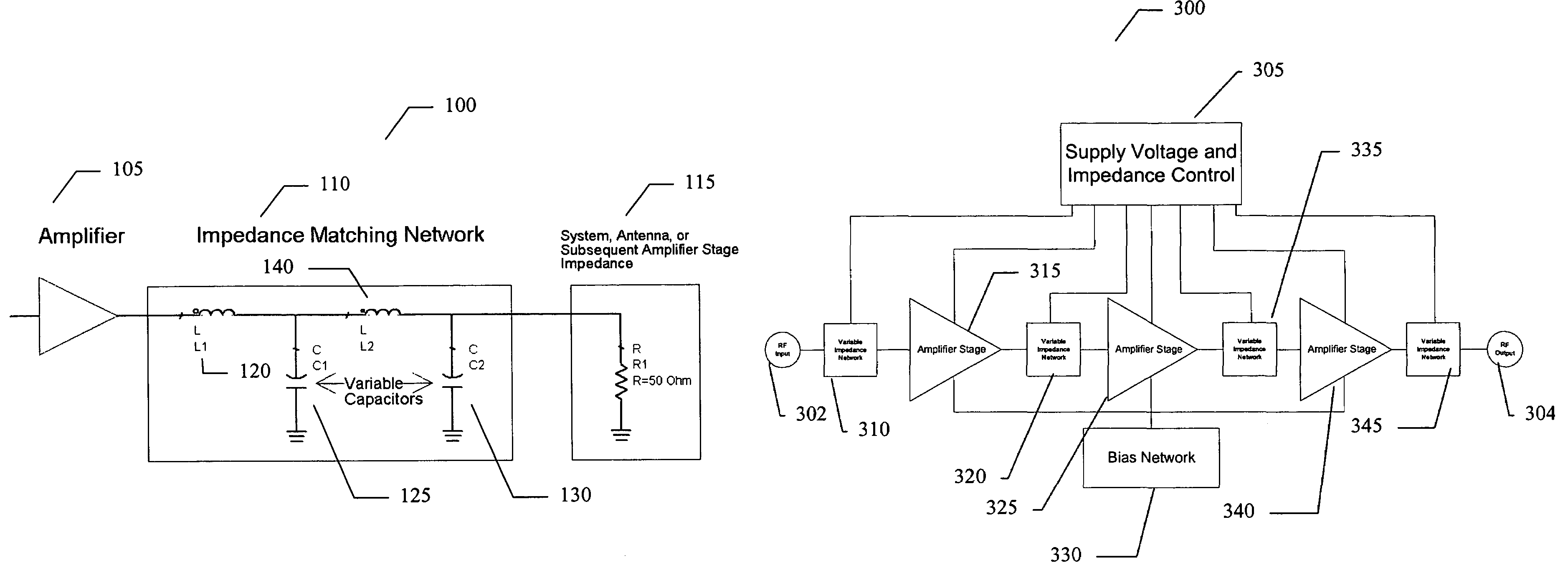
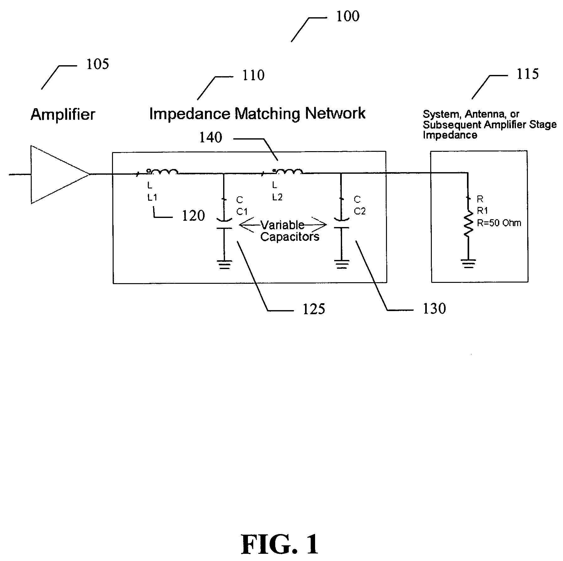
The present invention provides an amplifier system that can operate in multiple modes and can vary its impedance to match different needs. This is achieved through a variable impedance matching network that includes at least one variable capacitor, such as a voltage tunable dielectric capacitor. The system can also include a controller to manage the impedance control. The technical effects of this invention include improved performance and flexibility of the amplifier system.

Problems solved by technology

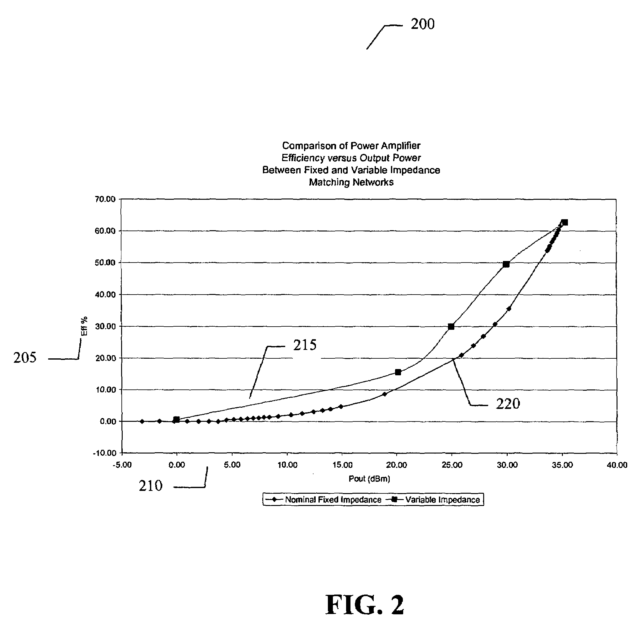
Different modulation schemes may place dramatically different requirements on the amplifier, leading to significant differences in ideal values for these variables.

Method used


Image

  • Amplifier system and method
  • Amplifier system and method
  • Amplifier system and method

Examples


Embodiment Construction

[0013]In the following detailed description, numerous specific details are set forth in order to provide a thorough understanding of the invention. However, it will be understood by those skilled in the art that the present invention may be practiced without these specific details. In other instances, well-known methods, procedures, components and circuits have not been described in detail so as not to obscure the present invention.

[0014]Use of the terms “coupled” and “connected”, along with their derivatives, may be used. It should be understood that these terms are not intended as synonyms for each other. Rather, in particular embodiments, “connected” may be used to indicate that two or more elements are in direct physical or electrical contact with each other. “Coupled” my be used to indicated that two or more elements are in either direct or indirect (with other intervening elements between them) physical or electrical contact with each other, and / or that the two or more element...


PUM


Abstract

An embodiment of the present invention provides an amplifier system, comprising at least one variable impedance matching network, the output of which provides the input to at least one amplifier stage or provides an output of the power amplifier itself, and a bias network associated with the at least one amplifier stage. The amplifier system may further comprise a controller enabling impedance control to the at least one variable impedance matching network and a supply voltage provided to the at least one variable impedance network and / or the at least one amplifier stage and wherein the at least one variable impedance network and the at least one amplifier stage may be a plurality of impedance networks connected to a plurality of amplifier stages. The at least one variable impedance network may include at least one variable capacitor and the at least one variable capacitor may be a voltage tunable dielectric capacitor which may include Parascan® voltage tunable dielectric material.

Description

CROSS-REFERENCE TO RELATED APPLICATION[0001]This application claims the benefit of priority under 35 U.S.C Section 119 from U.S. Provisional Application Ser. No. 60 / 554,025, filed Mar. 17, 2004, entitled, “Tunable PA Output Match”.BACKGROUND OF THE INVENTION[0002]Amplifiers, particularly those employed in modern wireless communication networks, may have a variety of possible modes of operation. The optimum mode of operation depends upon the format of data transmission or modulation scheme and the frequency of transmission. Amplifier design variables such as transistor sizes, supply voltages, bias points, and impedances for the source and load are chosen to insure optimized efficiency, linearity, and gain control while meeting the specifications of a given transmission scheme. Different modulation schemes may place dramatically different requirements on the amplifier, leading to significant differences in ideal values for these variables.[0003]In a typical amplifier most, if not all,...

Claims


Application Information

Patent Timeline
Patent Type & Authority Patents(United States)
IPC IPC(8): H03F3/04H03F1/02H03F1/56H03F3/189H03F3/191H03F3/68
CPCH03F1/0211H03F1/565H03F3/189H03F3/68H04B1/0458H03F2200/222H03F2200/318H03F2200/387H03F2200/451
Inventor MARTIN, JAMESKHAYO, IZZACKEENAN, RICHKARAVANIC, VALTERMENDOLIA, GREG
Owner NXP USA INC
Learn More