Interleaf removal apparatus, plate feed apparatus and image recording system

a technology of interleaf and plate feed, which is applied in the field of interleaf removal apparatus, plate feed apparatus and image recording system, can solve the problems of interleaf interleaf wrinkles or not being placed in a proper position, and interleaf often clinging to the plate, so as to prevent paper jams in the rotatable holding element more effectively

Inactive Publication Date: 2006-12-26
DAINIPPON SCREEN MTG CO LTD
View PDF4 Cites 9 Cited by
  • Summary
  • Abstract
  • Description
  • Claims
  • Application Information

AI Technical Summary

Benefits of technology

[0017]Thus, a direction in which wrinkles in the interleaf are removed is coincident with the direction of the rotation axis of the rotatable holding element. This prevents a paper jam in the rotatable holding element more effectively.

Problems solved by technology

Unfortunately, an interleaf often clings to a plate because of static electricity and the like.
In some rare cases, an interleaf stored in the cassette is wrinkled or is not placed in a proper position.
For example, a plate being taken out of the cassette drags an interleaf underlying the plate to consequently cause wrinkles in the interleaf.
Wrinkles in the interleaf might result in a danger that a paper jam occurs when the interleaf taken out is removed outwardly from the interleaf removal apparatus.

Method used


Image

  • Interleaf removal apparatus, plate feed apparatus and image recording system
  • Interleaf removal apparatus, plate feed apparatus and image recording system
  • Interleaf removal apparatus, plate feed apparatus and image recording system

Examples


Embodiment Construction

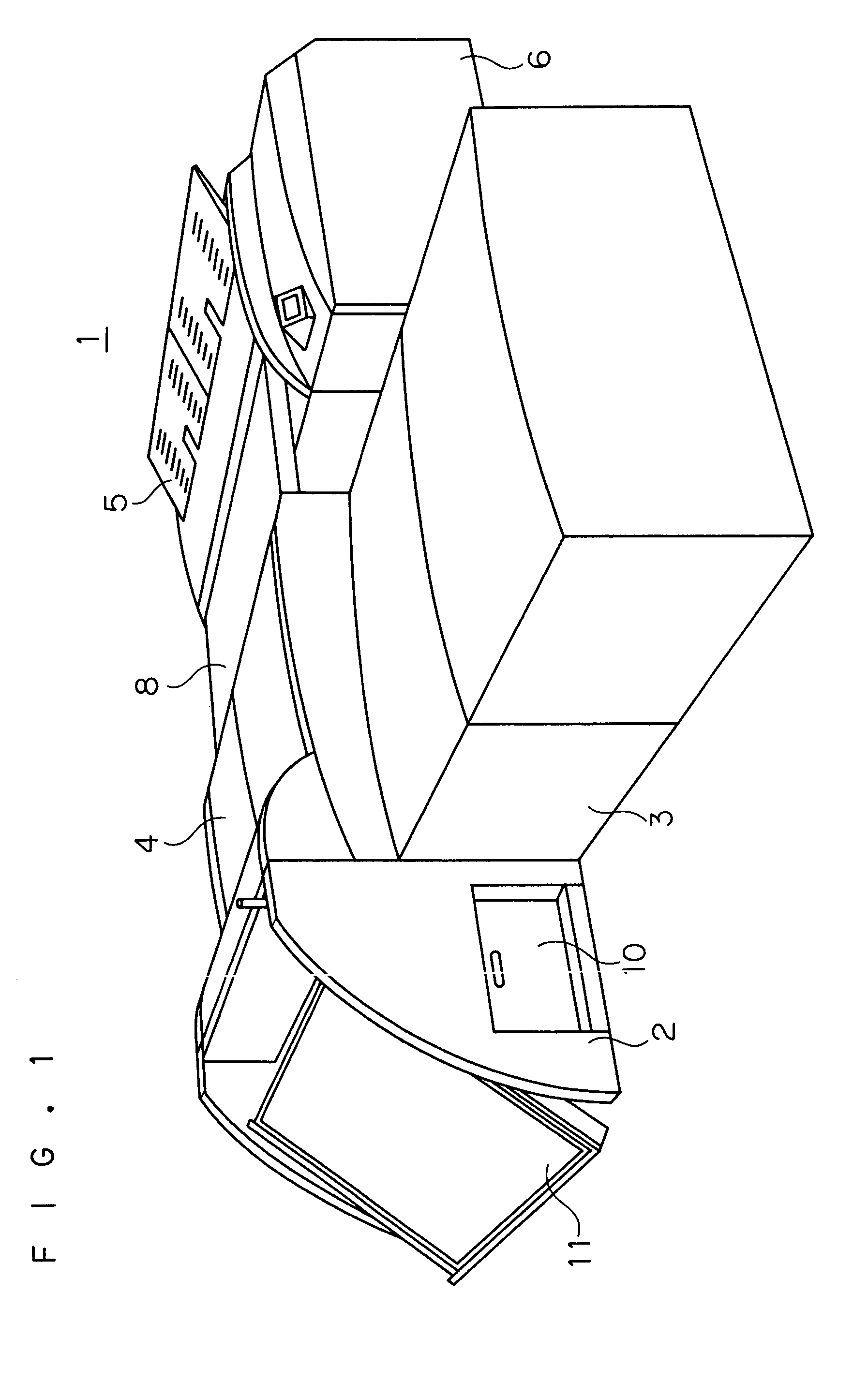
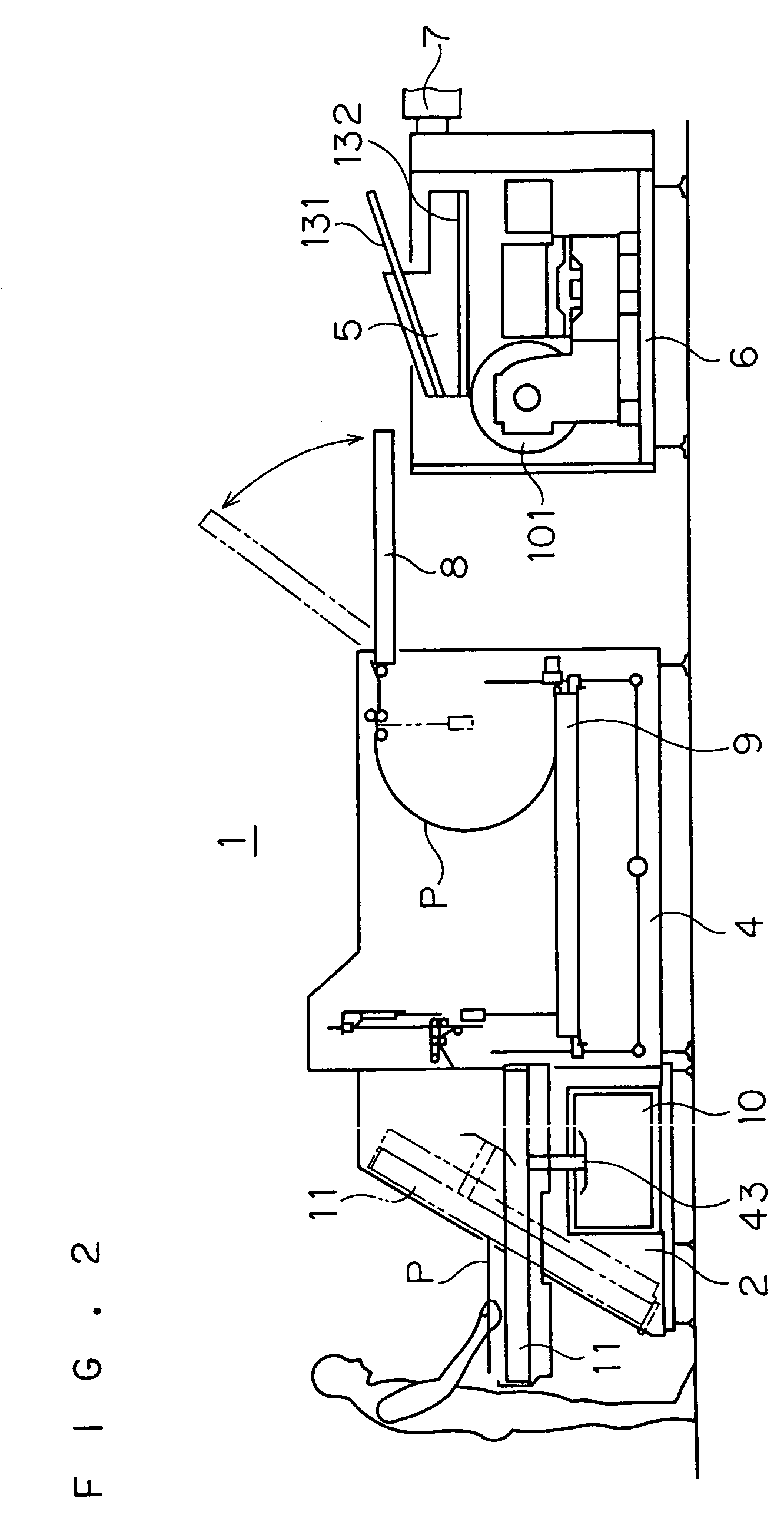
[0036]A preferred embodiment according to the present invention will now be described with reference to the drawings. FIG. 1 is a perspective view of an image recording system 1 including a plate feed apparatus according to the present invention. FIG. 2 is a schematic side view of the image recording system 1, and FIG. 3 is a schematic plan view thereof.

[0037](Image Recording System)

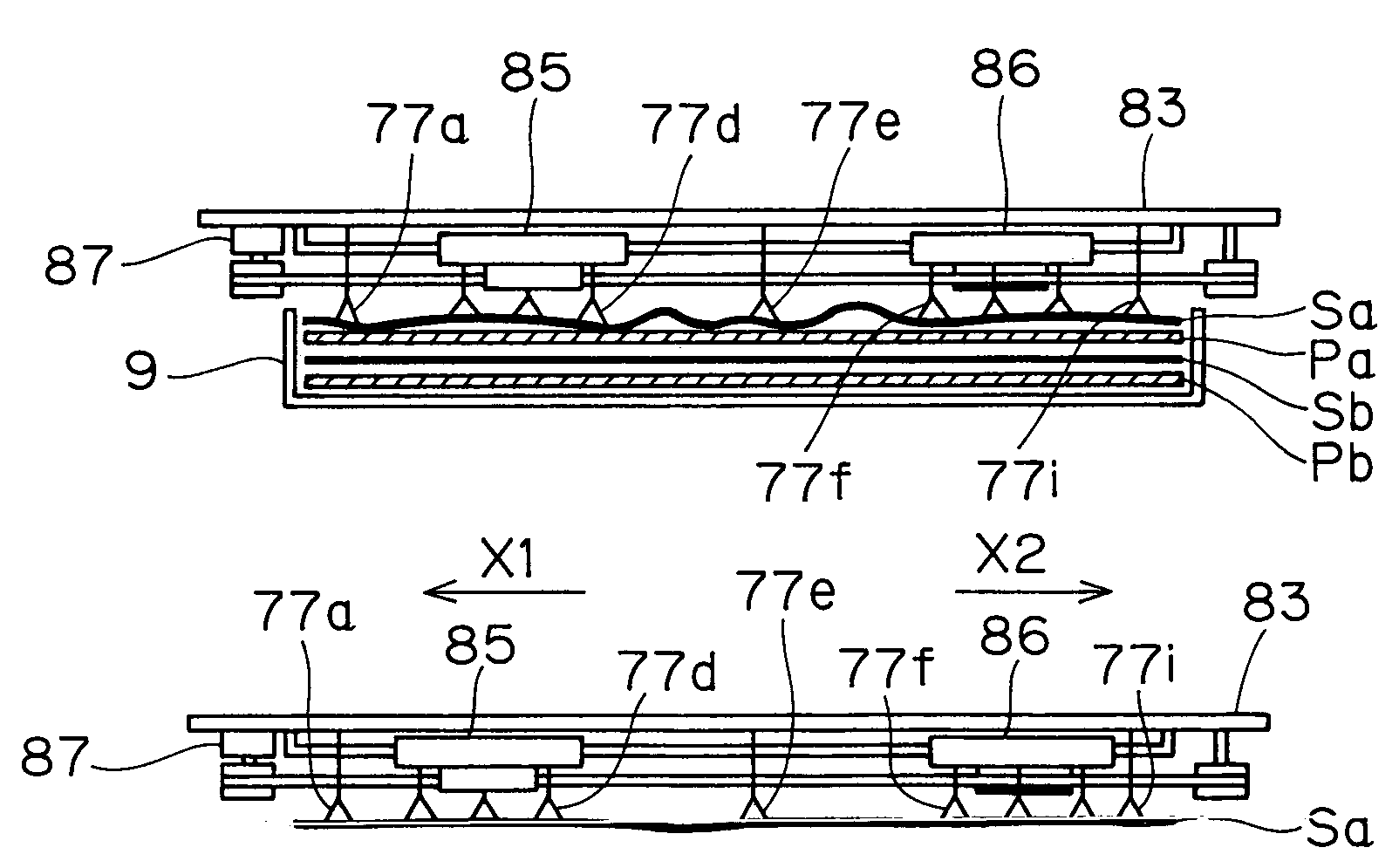
[0038]The image recording system 1 comprises a plate storage part 2, a multi-cassette part 3, an autoloader part 4, a feed / discharge tray part 5, an image recording part 6, a transfer mechanism 7, and a conveyor part 8. The plate storage part 2 is used when storing plates P in a cassette 9. The multi-cassette part 3 holds a plurality of cassettes 9 arranged vertically in multiple tiers. The autoloader part 4 acts to remove a plate P out of a cassette 9 in a predetermined plate feed position. The feed / discharge tray part 5 has a plate feed tray 131 and a plate discharge tray 132, and is provided to transf...


PUM


Abstract

An interleaf at the top position of a stack of plates and interleaves stored in a cassette is removed by attaching the interleaf to suction pads mounted to a vertically movable support. When the interleaf in the cassette is moved upwardly to a position opposed to a pair of nip rollers, movable suction pads move horizontally in such a direction as to stretch the interleaf to remove wrinkles in the interleaf. Then, a leading edge portion of the interleaf is held between the pair of nip rollers and removed outwardly.

Description

BACKGROUND OF THE INVENTION[0001]1. Field of the Invention[0002]The present invention relates to an interleaf removal apparatus for removing interleaves (also referred to as slip sheets) each between a plurality of plates for protection of the surfaces of the plates out of a storage part in which these plates are stored in a stacked relationship, in a plate feed apparatus for an image recording system for recording an image on a plate.[0003]2. Description of the Background Art[0004]A plate feed apparatus automatically feeds a plate to an image recorder and the like for recording an image on the plate by directing an optical beam such as laser light onto the plate. An interleaf removal apparatus is used in such a plate feed apparatus.[0005]A plurality of plates and a plurality of interleaves are alternately vertically stacked in a cassette in the plate feed apparatus.[0006]The interleaf removal apparatus removes an interleaf underlying a plate outwardly from the plate feed apparatus ...

Claims


Application Information

Patent Timeline
Patent Type & Authority Patents(United States)
IPC IPC(8): B65H3/08B41L47/14
CPCB65H3/0833B65H2404/1441B65H2701/18264B65H2701/1928
Inventor MIYOSHI, HIROSHI
Owner DAINIPPON SCREEN MTG CO LTD
Why Eureka
Try Eureka