Projectile with a sub-caliber penetrator core

a technology of penetrator core and projectile, which is applied in the direction of ammunition projectiles, ammunition fuzes, weapons components, etc., to achieve the effect of increasing the effect of the explosion on the targ

Inactive Publication Date: 2006-12-26
SAAB BOFORS DYNAMICS SWITZERLAND
View PDF6 Cites 9 Cited by
  • Summary
  • Abstract
  • Description
  • Claims
  • Application Information

AI Technical Summary

Benefits of technology

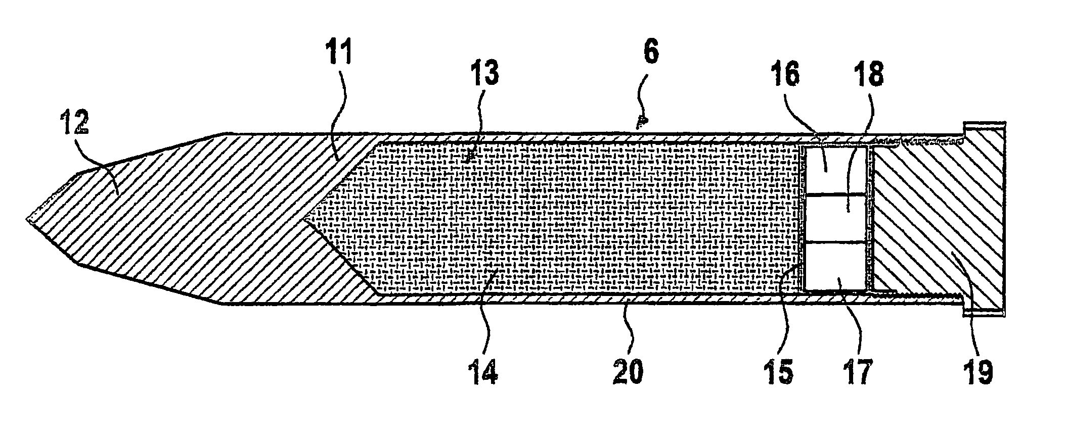
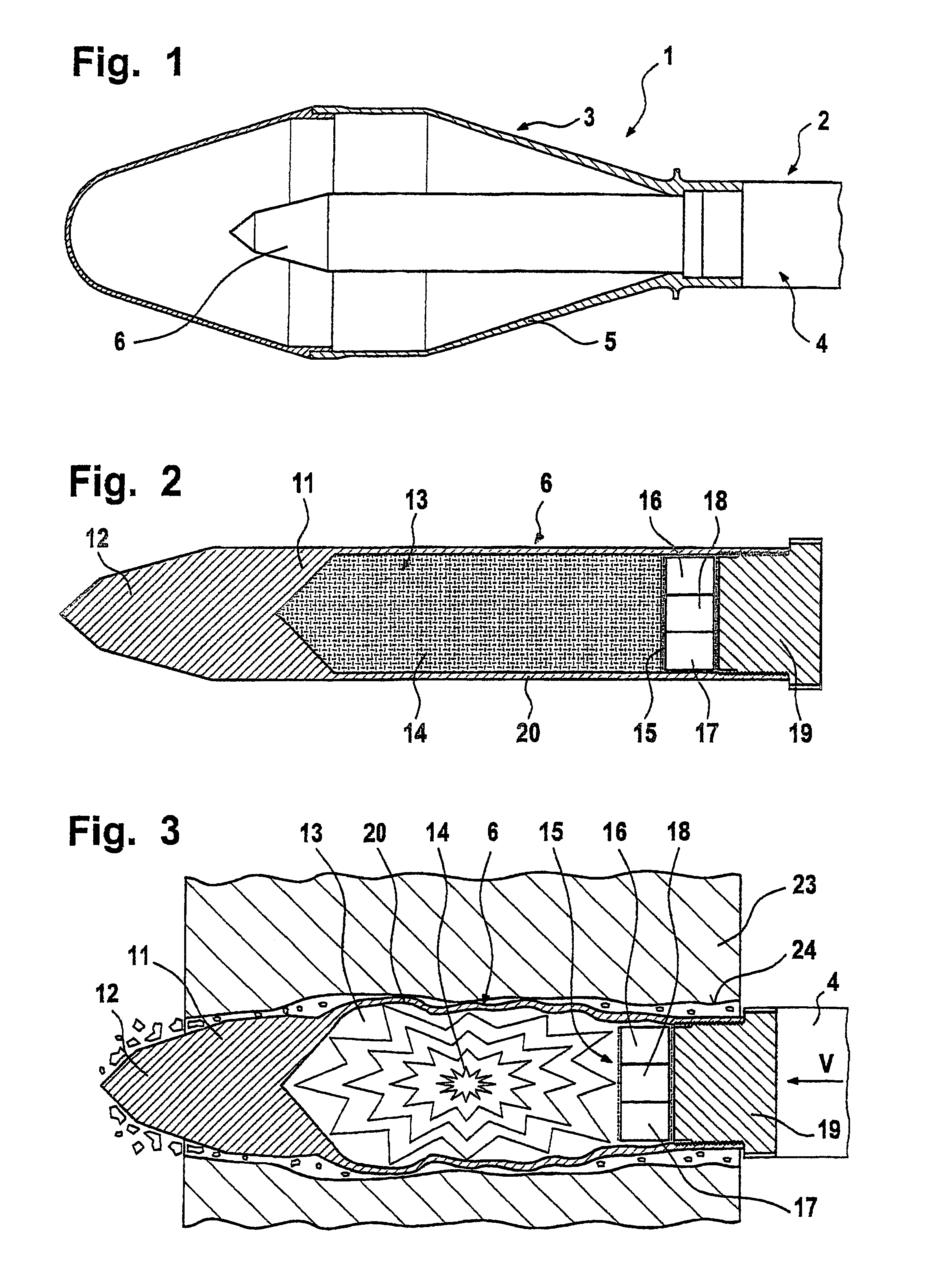
[0005]In accordance with the foregoing, the present invention aims at increasing the efficiency of the projectile at the target. This aim is achieved according to the invention by a projectile with an impact speed below 600 m / s. The projectile comprises a sub-caliber penetrator core with a cavity containing an explosive charge and a fuse. The fuse has a time delay circuit. The time delay adjusted in the time delay circuit is set such that the explosive charge is fired while the penetrator core is within a wall or other barrier to be penetrated or pierced.
[0006]Whereas the penetrator core according to U.S. Pat. No. 6,672,218 only creates a small diameter hole in the penetrated wall corresponding to the diameter of the penetrator core, the projectile according to the present invention creates a substantially larger hole. In a test firing, a brick wall of 1 m×1 m and 37.5 cm thickness was completely crumbled. In reinforced concrete walls the effect is somewhat lessened.
[0008]Preferably, the penetrator core comprises a massive metallic body both in front and behind the cavity. Thus, the hole in the target created by the penetrator core is dammed off on both sides as the explosive charge is fired. This substantially increases the effect of the explosion on the target. The fuse may be included in the rear metallic body.

Problems solved by technology

While projectiles of the type set forth in U.S. '218 are able to penetrate a wall for the purpose of releasing an active substance beyond the wall, the wall cavity produced by the projectile is rather small, and thus may be of limited value in providing an entranceway through the wall for the further passage of projectiles; equipment or personnel.

Method used


Image

  • Projectile with a sub-caliber penetrator core
  • Projectile with a sub-caliber penetrator core

Examples


Embodiment Construction

[0013]FIG. 1 shows the front part of a projectile 1. The projectile 1 comprises a rear part 2 and a forward part 3. The rear part 2 includes a propulsion unit 4 (rocket) and stabilizing fins at its rear end (not shown). These elements may be identical to the propulsion unit and stabilizer fins of other projectiles fired from commonly known weapons such as bazookas, missile launchers or mortars, so that the projectile 1 according to the present invention can be fired from such weapons.

[0014]The forward part 3 comprises a relatively thin walled aluminum shell 5 and a sub-caliber penetrator core 6 mounted in the shell 5. The shell 5 is mounted on the propulsion unit 4 in the same way that a standard or conventional shaped charge warhead of a bazooka is mounted on the propulsion unit 4. The outside dimensions of the shell 5 are the same as the ones of the standard warhead for that weapon. That way the gunner, who is trained to handle his, e.g., shoulder fired weapon against armoured tar...


PUM


Abstract

A low-speed projectile is designed for forming relatively large apertures in walls against which the projectile is fired. The projectile includes a penetrator core having a cavity containing an explosive charge activated by a time delay fuse circuit. The time delay is chosen to cause explosive ignition when the cavity and explosive is within the wall to be pierced. The construction of the projectile directs the explosive impulse radially, creating a hole in the wall considerably larger than the outside diameter of the penetrator's core. A preferred application is a projectile for a shoulder-fired weapon.

Description

FIELD AND BACKGROUND OF THE INVENTION [0001]The present application is a continuation of PCT / IB03 / 01139, filed 25 Mar. 2003, and relates to a projectile with an impact speed below 600 m / s, the projectile comprising a sub-caliber penetrator core. A projectile of this general type is known from U.S. Pat. No. 6,672,218 (hereinafter referred to as “U.S. '218”), the teachings of which are incorporated herein by reference. The projectile has an outer shell corresponding in its outside dimensions to a conventional bazooka shaped charge warhead. The projectile can therefore be fired by conventional bazooka rocket weapon launch equipment. In contrast to a conventional bazooka warhead, the projectile according to U.S. '218 comprises a relatively massive penetrator core of reduced diameter which can pierce brick or concrete walls, sand bag shielding or light armor plates. The penetrator core has a cavity which may contain a non-lethal active substance which is spread into the space behind the ...

Claims


Application Information

Patent Timeline
Patent Type & Authority Patents(United States)
IPC IPC(8): F42B12/02F42B12/06F42B12/20F42C1/12
CPCF42B12/06F42B12/204F42C1/12
Inventor CONRAD, MARKUS MARCELLUS
Owner SAAB BOFORS DYNAMICS SWITZERLAND
Why Eureka
Try Eureka