
Method and apparatus for reducing printing artifacts of stitched images

Inactive Publication Date: 2006-12-26
THE PERKIN ELMER CORP
View PDF44 Cites 18 Cited by
  • Summary
  • Abstract
  • Description
  • Claims
  • Application Information

AI Technical Summary

Benefits of technology

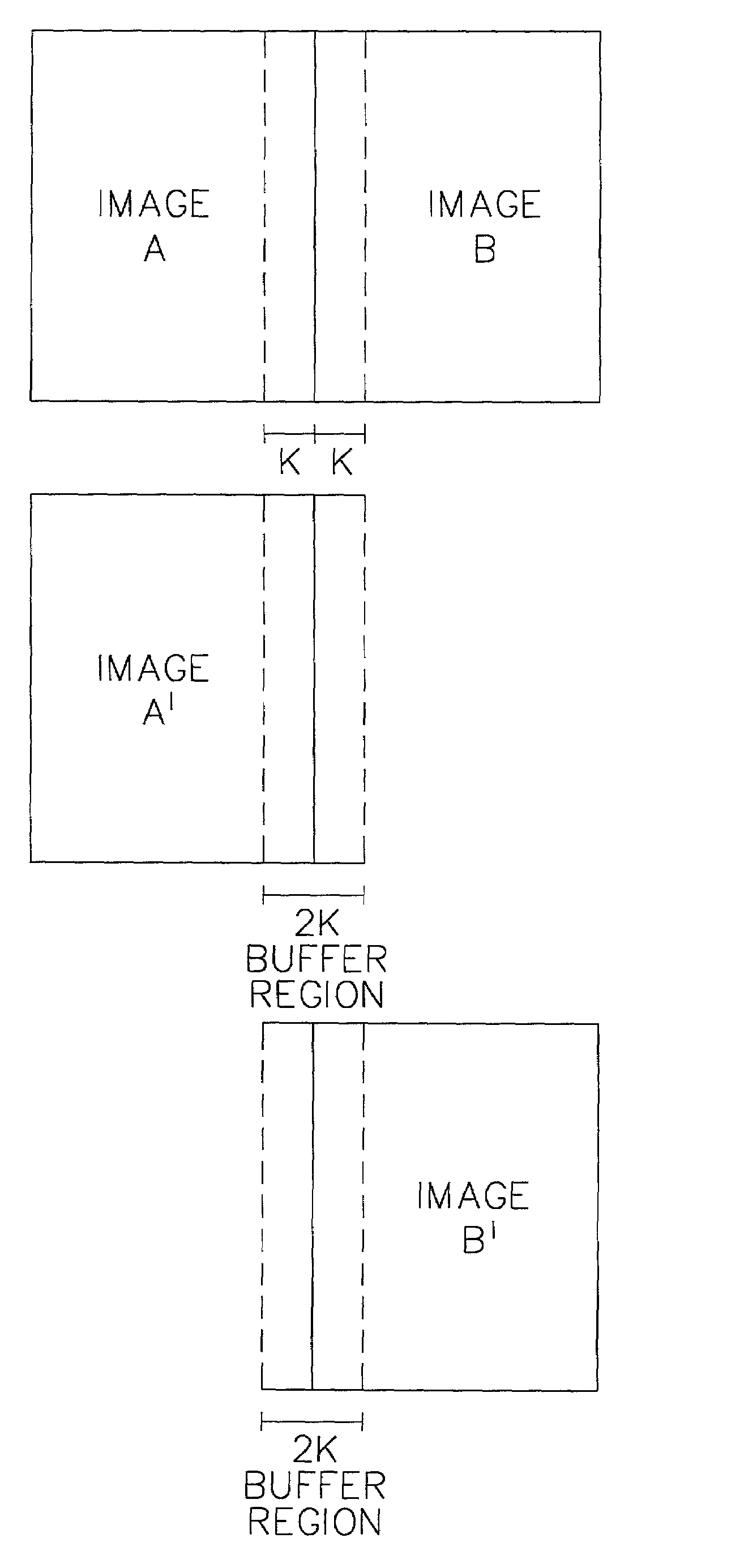
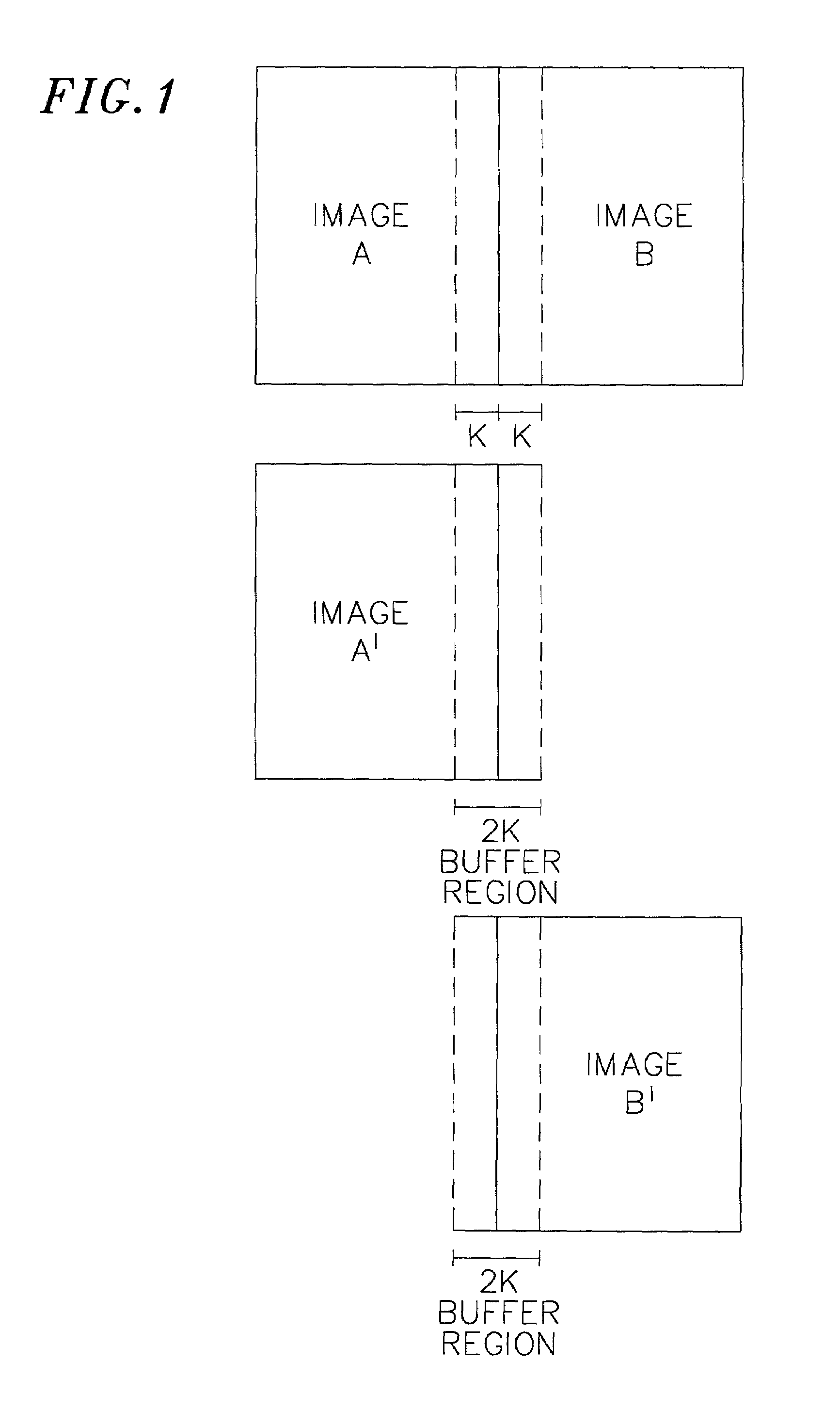
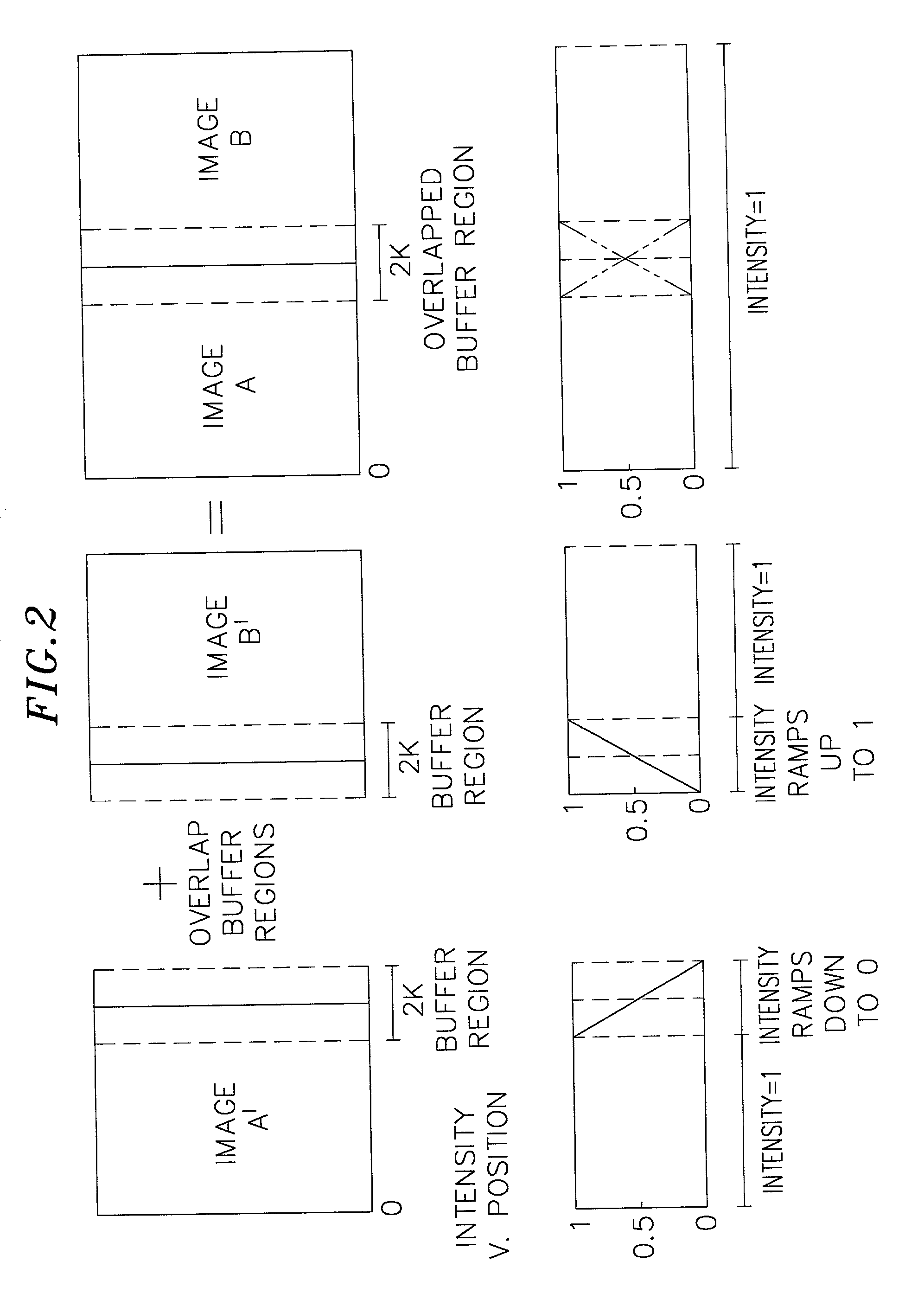
[0009]The present invention provides various methods and apparatus for eliminating artifacts in an image formed using more than one image segment. For example, the present invention provides a unique stitching method for eliminating visible seams in the image by creating a first buffer region in a first image segment in which the intensity of the pixels in the first buffer region is attenuated, a buffer region in a second image segment in which the intensity of the pixels in the second buffer region is attenuated, and then overlapping the buffer regions of the two image segments. The present invention provides for the buffer region to be defined as an area of an image comprising a number of pixels from one image segment and a number of pixels from an adjacent image segment. The present invention further provides in a particular preferred embodiment that the intensity of the pixels in the buffer region of each image segment may be attenuated by the use of a device to modulate the intensity of the scanning beam or beams.

Problems solved by technology

However, in flatbed raster recording systems, such as computer-to-plate systems, technical and cost hindrances limit the practical length of the scan line.
In an attempt to overcome this page width limitation, efforts have been made, with limited success, to combine the partial scan lines produced by more than one imaging source, or produced by one source at different times, into a single, composite image.
However, it is difficult to precisely butt two printed pages together.
Additional artifacts produced by cross-scan errors, pixel size variations, exposure variations and other factors, may also be introduced, further diminishing the quality of the composite image.
An undesirable source of error in optical scanning systems results from in-scan error.
In-scan error specifically refers to errors in the placement of scan lines in a direction parallel to the lines themselves.
Sources of in-scan errors may include variations in the rotational speed of the polygon mirror, pixel timing, clock jitter and mechanical errors such as bearing noise and facet rotational error.
Past attempts to join multiple image segments together have been largely unsuccessful at eliminating a visible seam where the image segments have been joined or have involved complex processing.

Method used


Image

  • Method and apparatus for reducing printing artifacts of stitched images
  • Method and apparatus for reducing printing artifacts of stitched images
  • Method and apparatus for reducing printing artifacts of stitched images

Examples


Embodiment Construction

[0014]In a typical flatbed laser raster output scanner, an image is generated by “painting” a two dimensional raster image. One dimension is generated by scanning the laser beam or beams in the “fast scan” (horizontal) direction while the other dimension is generated by more slowly transporting the object or recording medium in a direction orthogonal to the fast scan (vertical or “slow scan”). The source of the printed data is typically generated from a database that is usually arranged in a rectilinear bitmap to be compatible with the raster scanned cathode-ray tube display and usually consists of digital data in binary form, either text or halftone images. In other words, the intensity of any one pixel may only be one of two levels of gray. However, in some cases, data for the raster image may be multi-level data. The exposed object is typically a photosensitive surface such as a printing plate, a xerographic drum, silver-halide film, or other photosensitive coated substrate. Alth...


PUM


Abstract

A method and apparatus for eliminating artifacts in images formed using more than one image segment. A buffer region associated with two adjacent image segments is defined wherein the intensity levels of the pixels are attenuated. When image segments substantially overlap in the buffer region, the intensity in the buffer region substantially sums to full scale. The intensity of the pixels in the buffer region is preferably attenuated using a device to modulate the intensity of the source of radiation.

Description

FIELD OF THE INVENTION[0001]The present invention is in the field of exposure systems. More particularly, the present invention provides a method and apparatus for combining (“stitching”) more than one image segment to produce a larger image without creating a visible seam or other artifacts at the interface between the multiple image segments.BACKGROUND OF THE INVENTION[0002]Raster output scanning is commonly used in a number of applications, including flatbed scanning recorders, capstan imagesetters and platesetters and even some external or internal drum systems. In a typical flat field imaging application, a photosensitive material, for example, is moved at constant speed by a capstan roller or other linear conveyor means, fed from continuous rolls or precut cassettes of stacked material to present the material to a stationary optical system for scanning. Alternatively, stationary photo-sensitive material may be imaged by translating the optical system. The scan optic in the fla...

Claims


Application Information

Patent Timeline
IPC IPC(8): G09G5/06B41B1/00B41J1/00G06FG06F15/00G06K1/00G06K15/12G06T15/50G06T15/60G09G5/00G09G5/02
CPCG06K15/12G06K15/1247G06K2215/111
Inventor DONAHUE, JOSEPH P.HART, WILLIAM A.
Owner THE PERKIN ELMER CORP
Learn More