Magnetic resonance imaging apparatus and image processing method

Pending Publication Date: 2021-10-28
FUJIFILM HEALTHCARE CORP
View PDF0 Cites 1 Cited by
  • Summary
  • Abstract
  • Description
  • Claims
  • Application Information

AI Technical Summary

Benefits of technology

[0012]According to the present invention, it is possible to eliminate the artifact caused by combining the

Problems solved by technology

One of the technical problems in the MRI is a shortening of the imaging time.
Various shortening methods have been proposed, but shortening the imaging time is accompanied by a decrease in the signal-to-noise ratio (SNR).
When performing such zero-fill reconst

Method used


Image

  • Magnetic resonance imaging apparatus and image processing method
  • Magnetic resonance imaging apparatus and image processing method
  • Magnetic resonance imaging apparatus and image processing method

Examples


Example

Embodiment 1

[0046]In the present embodiment, utilizing the fact that an artifact caused by noise removal using the zero-fill reconstruction and Wavelet transform appears as a characteristic artifact in a high-frequency region of the k-space, a region is created where the artifact is made occur by extending k-space data of an image in a pre-processing, and then, processing of cutting this area is performed as a post-processing.

[0047]With reference to the flowchart of FIG. 6, the processing of the noise remover 230 in the present embodiment will be described. In the present embodiment, measurement data of the acquisition matrix smaller than the reconstruction matrix is also obtained, the measurement data is arranged in the k-space, and the zero-fill reconstruction is performed as in the processing of FIG. 4 (S601).

[0048]In the present embodiment, the pre-processing unit 231 (FIG. 3) performs the pre-processing on the image obtained by the zero-fill reconstruction, prior to the noise r...

Example

Embodiment 2

[0055]In the present embodiment, similar to Embodiment 1, the pre-processing of an image of interest is performed prior to noise removal, and after the noise removal, the post-processing is performed to restore the image to the original reconstruction matrix. In the present embodiment, however, it is featured that cutting out is performed to a size larger than or equal to the acquisition matrix and smaller than the reconstruction matrix in the pre-processing, and then in the post-processing, the size is restored to that of the original reconstruction matrix. Since the configuration and processing of the noise remover 230 are the same as those shown in FIGS. 3 and 6, the pre-processing S602 of FIG. 6 will be hereinafter referred to as S612, and the post-processing S604 will be referred to as S614, to describe the details. FIGS. 9A and 9B show the details of the pre-processing and the post-processing.

[0056]As shown in FIG. 9A, in the pre-processing (S612), the pre-processi...

Example

Embodiment 3

[0062]In the present embodiment, it is featured that in the course of noise removal, a characteristic of artifact is extracted, and a filter for eliminating the artifacts is created, so as to remove only the artifact.

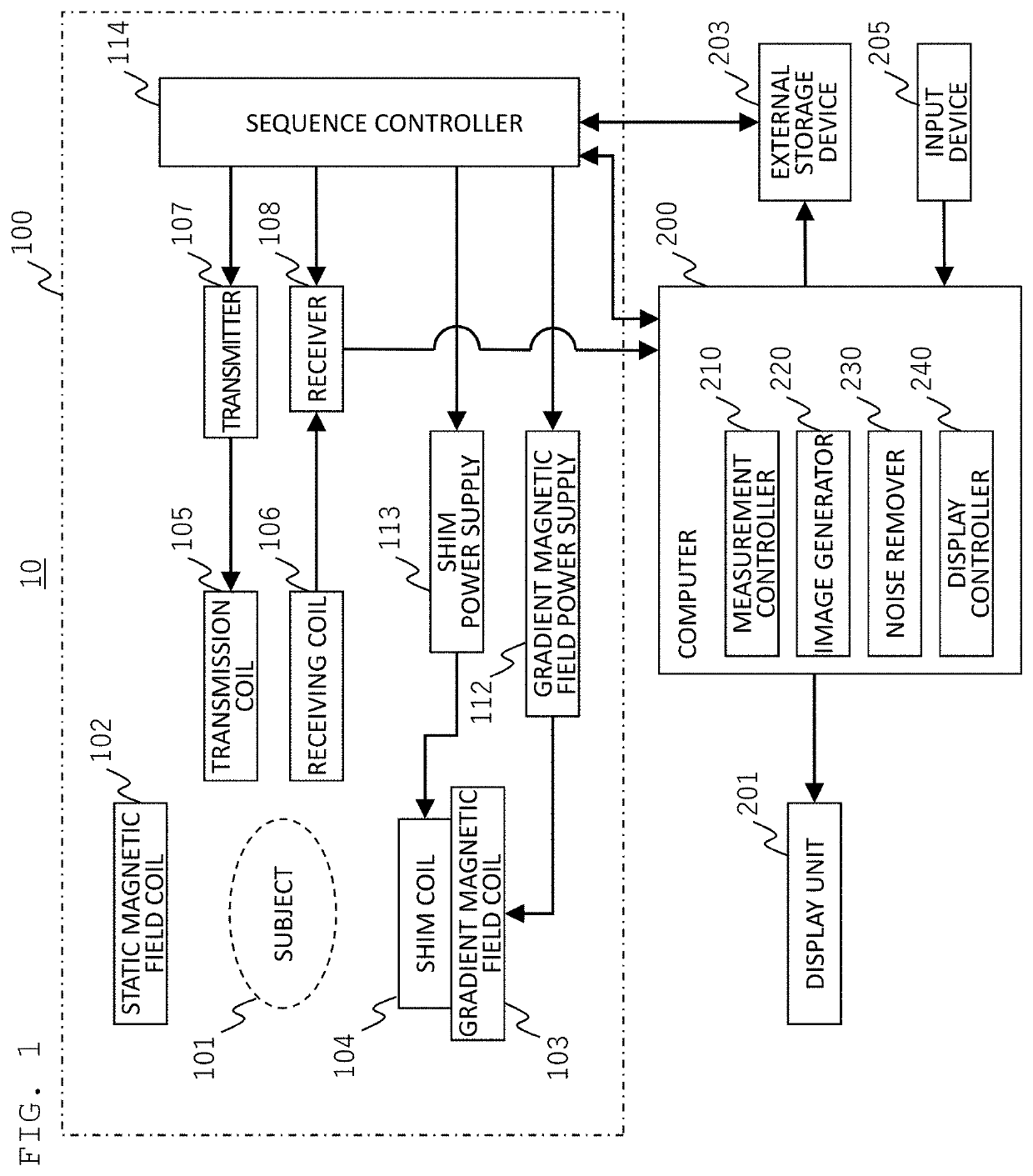
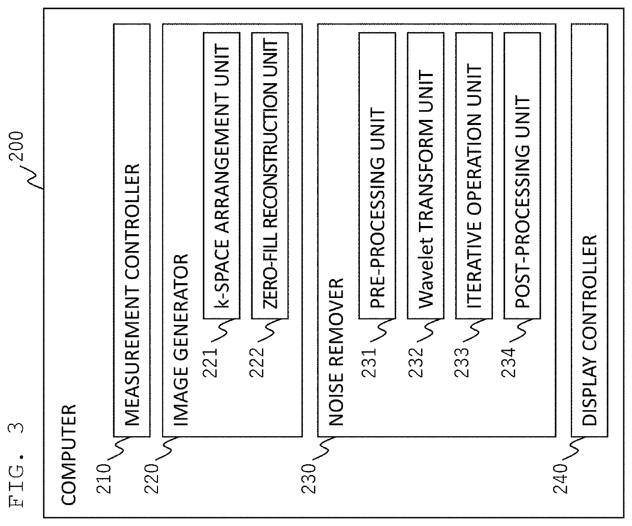
[0063]FIG. 11 illustrates a configuration of the noise remover 230 of the present embodiment. In the present embodiment, the noise remover 230 includes, in addition to the Wavelet transform unit 232 and the iterative operation unit 233, a noise extracting unit 236 for extracting noise from an image after the Wavelet transform to create a noise image, an artifact prediction unit 237 for predicting an artifact signal from the noise image created by the noise extracting unit 236, and a window function creating unit 238 for creating a window function (filter) for eliminating the artifact.

[0064]There will now be described the processing of the noise remover 230, mainly focusing on the processing of those units as mentioned above. FIG. 12 shows the outline of the ...


PUM


Abstract

Provided is a magnetic resonance imaging apparatus with no occurrence of artifacts, even after noise removal by applying Wavelet transform to a zero-fill reconstructed image. Nuclear magnetic resonance signals acquired by the magnetic resonance imaging apparatus are processed to perform reconstruction with a reconstruction matrix extended by zero-filling an acquisition matrix, and then a zero-fill reconstructed image is produced. This reconstructed image is subjected to an iterative operation combining the Wavelet transform and L1 norm minimization to remove noise. Before the noise removal, a pre-processing is performed to change the reconstruction matrix size so that an artifact does not occur in the image after noise removal, an artifact portion appears outside the reconstruction matrix after the noise removal, or cutting out is performed so that no artifact appears after the noise removal. The matrix size is restored to its original size in the post-processing after the noise removal.

Description

INCORPORATION BY REFERENCE[0001]The present application claims priority from Japanese patent application JP-2020-079606 filed on Apr. 28, 2020, the content of which is hereby incorporated by reference into this application.BACKGROUND OF THE INVENTIONField of the Invention[0002]The present invention relates to a magnetic resonance imaging apparatus (hereinafter, referred to as MRI apparatus), and more particularly, it relates to a technique for eliminating artifacts after removing noise of an image, the artifacts being caused by the noise removal.Description of the Related Art[0003]An MRI apparatus is a noninvasive medical imaging diagnostic equipment utilizing nuclear magnetic resonance phenomena in which hydrogen atomic nuclei (protons) placed in a static magnetic field resonate to high frequency magnetic field of a specific frequency. Since MRI can capture images of various tissue contrast depending on imaging methods and imaging parameter change, it is possible to acquire informa...

Claims


Application Information

Patent Timeline
IPC IPC(8): G01R33/56G06T3/40G16H30/40
CPCG01R33/5608G16H30/40G06T3/4084G01R33/5602A61B5/055A61B5/0033A61B5/7203G16H30/20
Inventor SHOJI, HIROKISHIRAI, TORUKUROKAWA, SHINJI
Owner FUJIFILM HEALTHCARE CORP
Why Eureka
Try Eureka