Point to multipoint network

a multi-point network and point-to-multi-point technology, applied in the field of point-to-multi-point networks, can solve the problems of increasing complexity, custom-designed integrated circuits are required, and the ranging process is considerable in complexity, and achieves the effect of shortening the time to market and cost-effective infrastructur

Active Publication Date: 2006-12-26
RPX CLEARINGHOUSE
View PDF7 Cites 10 Cited by
  • Summary
  • Abstract
  • Description
  • Claims
  • Application Information

AI Technical Summary

Benefits of technology

[0034]Multiple access networks allow fibre and exchange end equipment to be shared across groups of end customers, resulting in a more cost effective infrastructure.
[0035]Alternatively, this invention allows a multiple access network to be built without the need for active electronics in street locations. A network requiring only passive elements in outside locations would be more attractive, particularly to incumbent network operators who traditionally have not used active street equipment.
[0036]Advantageously, the possibility of reusing existing technology designed for Gigabit Ethernet offers the opportunity of achieving shorter time to market than developing entirely new technology for the system.

Problems solved by technology

A disadvantage of this approach is that the ranging process involves considerable complexity and custom designed integrated circuits are required at both the head end and the outstations in a practical system.
A further drawback is that because PON systems built according to FSAN principles normally use short packets for information transfer, transmission of data already formatted into larger packets requires these larger packets to be segmented for transport over the PON, adding further complexity.

Method used


Image

  • Point to multipoint network
  • Point to multipoint network
  • Point to multipoint network

Examples


Embodiment Construction

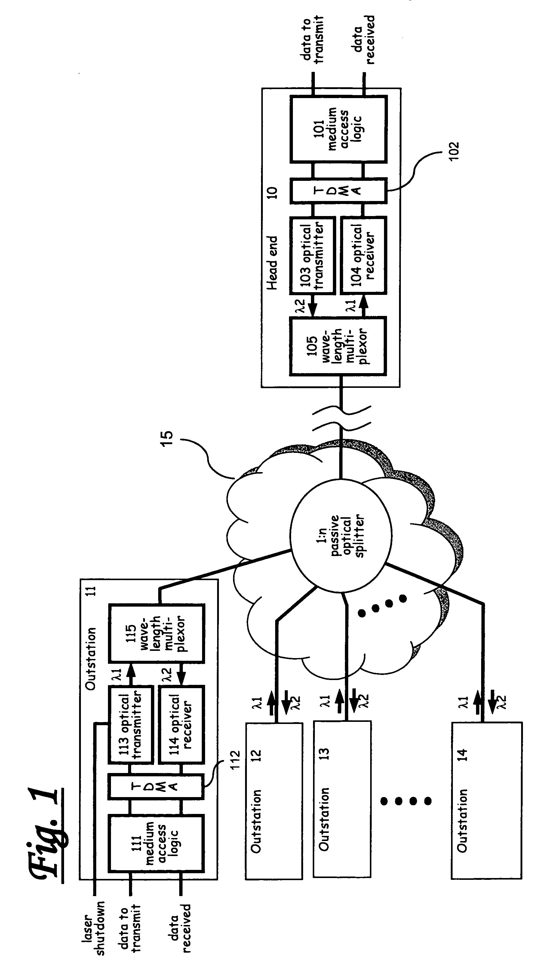
[0043]Referring to FIG. 1, there is shown an optical network arrangement comprising a head-end station 10 and, multiple subscriber stations 11–14 connected by a passive optical network 15.

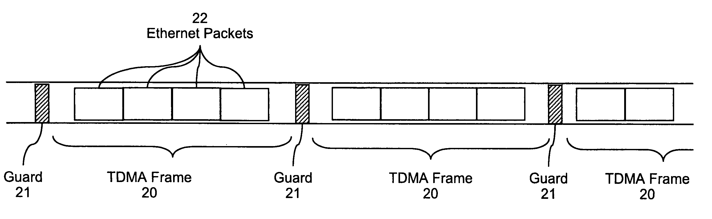
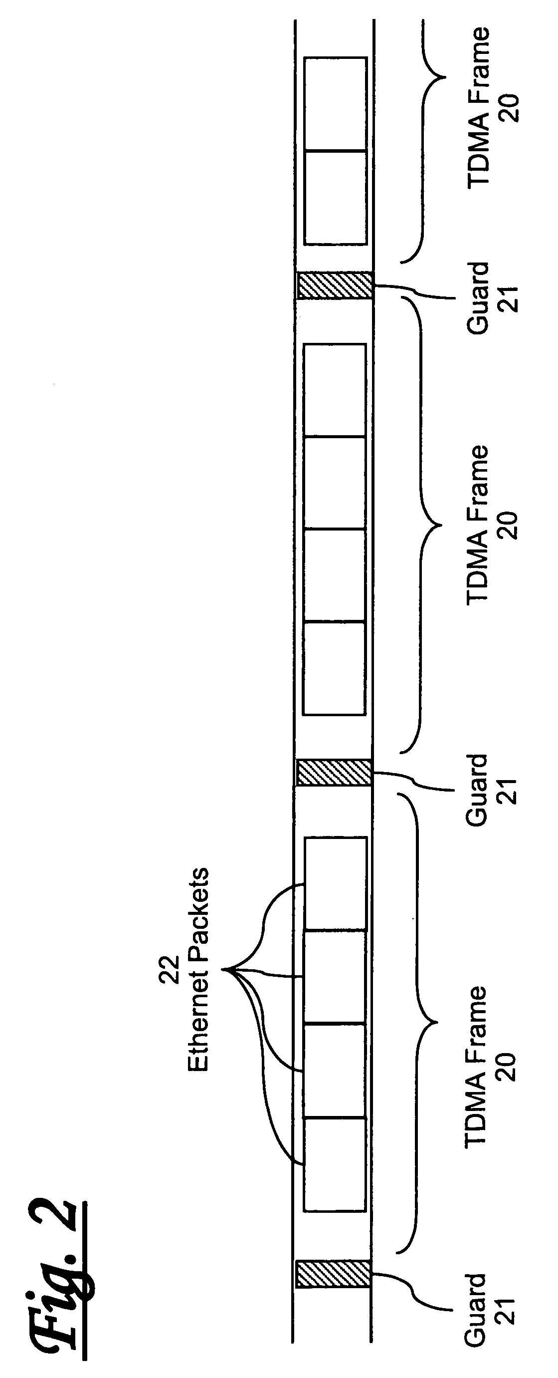
[0044]The system is arranged to provide an improved form of multiple access passive optical network, not based on small packets and ranging to achieve efficiency, but rather using variable sized (e.g. Ethernet) packets each able to carry IP traffic directly without segmentation.

[0045]The head-end station 10 comprises medium access logic 101 interfacing via a TDMA framing and sychronisation module 102 to optical transmitter 103, optical receiver 104, and hence to a wavelength multiplexer 105 which provides the physical interface to the optical network 15.

[0046]Each outstation 11–14 has a corresponding structure comprising medium access logic 111 connected via the TDMA framing and sychronisation module 112 to an optical transmitter 113 and optical receiver 114 and hence to a wavelength multiplexer 11...


PUM


Abstract

A point-to-multipoint network arrangement, method of operation and related signals for a network comprising a head-end station and at least one subscriber station connected to the head-end by means of a shared medium high-speed point-to-multipoint network (preferably a passive optical network). The method involves transmitting data upstream using a packet-switched transport protocol (e.g. Ethernet) over TDMA. By using high-speed upstream transmission with relatively long time slots and relatively short guard bands, the need for complex ranging schemes is obviated.

Description

RELATED APPLICATIONS[0001]This application is the full filing of the provisional application 60 / 207,800 filed May 30, 2000 and entitled “Gigabit Ethernet-Passive Optical Network” from which this application claims priority.FIELD OF THE INVENTION[0002]The present invention relates to a method and apparatus for providing a high capacity point-to-multipoint network, a system incorporating the same, and signals generated by such a system. This invention is particularly related to, but in no way limited to, point-to-multipoint networks, known as fibre to the user (FTTU).BACKGROUND TO THE INVENTION[0003]It is known to design point-to-multipoint access networks based on Passive Optical Networks (PONs). In a PON, a single head end is connected to a number of outstations via optical fibres connected in a tree-like arrangement using one or more passive distributive optical couplers to achieve optical fanout at the logical hub of the network. Typically, separate fibres and couplers are provide...

Claims


Application Information

Patent Timeline
Patent Type & Authority Patents(United States)
IPC IPC(8): H04L12/66
CPCH04J3/1694
Inventor PFEFFER, ROBERTMANN, DAVIDUNITT, BRIAN
Owner RPX CLEARINGHOUSE
Why Eureka
Try Eureka