Fabrication of microstructured fibres

a microstructured fibre and fabrication method technology, applied in the field of new methods of fabricating microstructured fibres, can solve the problems of poor cleanness, low longitudinal uniformity, and low reproducibility of microstructured fibres, and achieve low longitudinal uniformity, poor cleanness, and low reproducibility

Inactive Publication Date: 2006-12-26
CRYSTAL FIBRE AS
View PDF38 Cites 28 Cited by
  • Summary
  • Abstract
  • Description
  • Claims
  • Application Information

AI Technical Summary

Benefits of technology

[0043]Fabrication of microstructured fibres using stacking of a multitude of capillary tubes or using extrusion-based methods may be disadvantageous for a number of reasons, including low longitudinal uniformity, poor cleanness, low reproducibility, high polarization mode dispersion, limited flexibility of fibre design etc. The present inventors have, however, realized that the use of extrusion or a multitude of capillary tubes for

Problems solved by technology

Fabrication of microstructured fibres using stacking of a multitude of capillary tubes or using extrusion-based methods may be disadvantageous for a number of

Method used


Image

  • Fabrication of microstructured fibres
  • Fabrication of microstructured fibres
  • Fabrication of microstructured fibres

Examples


Embodiment Construction

[0130]Further scope of applicability of the present invention will become apparent from the detailed description given hereinafter. However, it should be understood that the detailed description and specific examples, while indicating preferred embodiments of the invention, are given by way of illustration only, since various changes and modifications within the spirit and scope of the invention will become apparent to those skilled in the art from this detailed description.

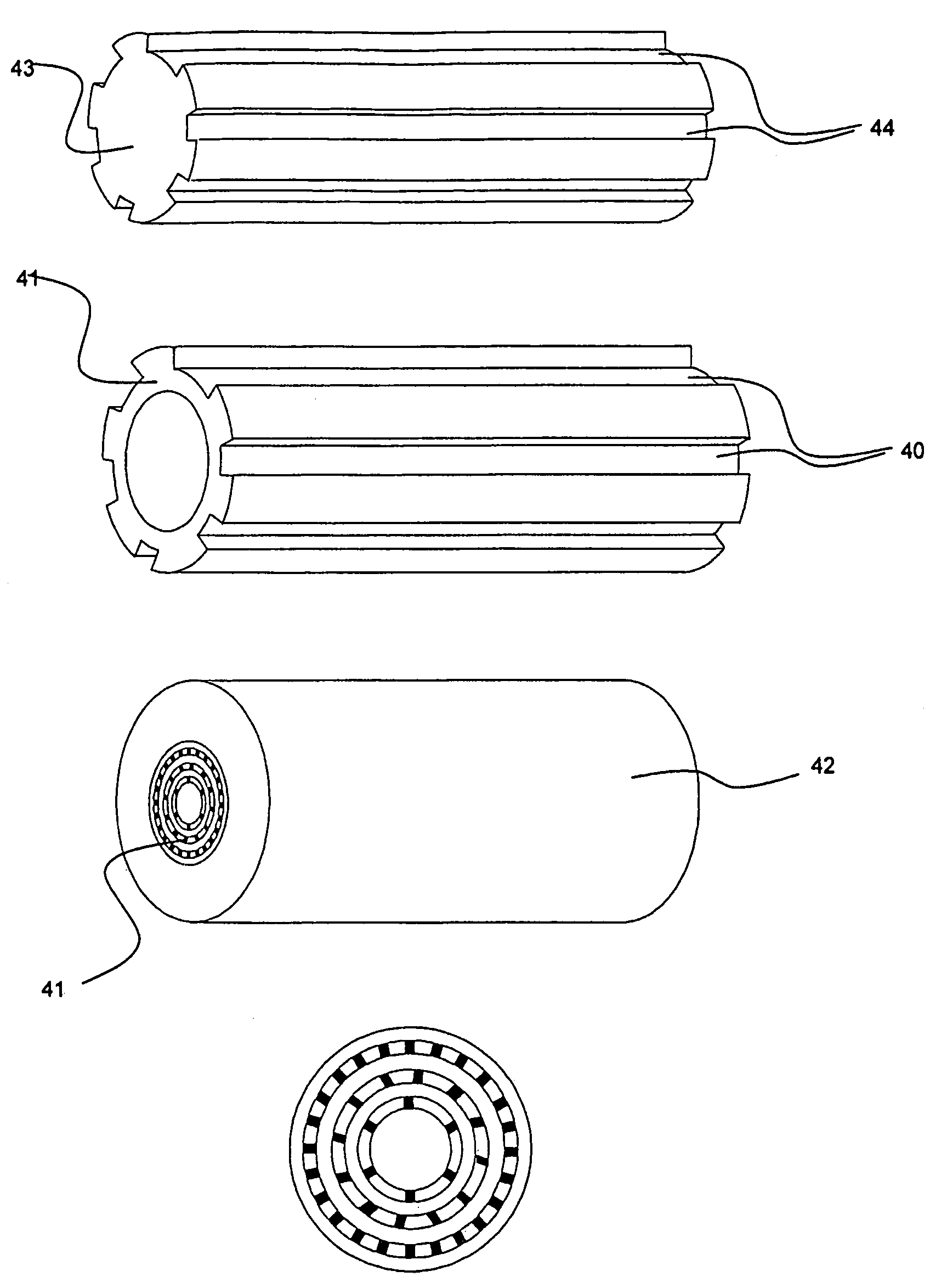
[0131]The present invention relates to a number of improvements for the realisation and use of microstructured fibres.

[0132]Microstructured fibres are generally divided into two types depending on the physical mechanism responsible for the light guidance: at an operating wavelength, index-guiding microstructured fibres are characterised by a core having a higher refractive index than a surrounding cladding region (as known from conventional optical fibres), and photonic bandgap microstructured fibres are characte...


PUM

PropertyMeasurementUnit
Temperatureaaaaaaaaaa
Lengthaaaaaaaaaa
Lengthaaaaaaaaaa

Abstract

A preform for a microstructured fibre or a part for a preform for a microstructured fibre. The preform or part has a length in the longitudinal direction and a cross section perpendicular thereto, and includes a rod arranged at the centre of the preform or part, with one or more tubes being concentric to the rod. The rod is sleeved inside a first of the concentric tubes, and the rod and/or at least one of the concentric tubes has grooves and/or slits extending in the longitudinal direction, with the number of innermost longitudinally extending grooves and/or slits with respect to a centre of the preform or part being at least six.

Description

[0001]This is a nationalization of PCT / DK02 / 00154 filed Mar. 9, 2002 and published in English.FIELD OF INVENTION[0002]The present invention relates to new methods of fabricating microstructured fibres providing improvements with respect to propagation losses, splicing losses, polarization mode dispersion, and other critical issues for practical development of microstructured fibres.BACKGROUND OF THE INVENTION[0003]Microstructured fibres, also known as photonic crystal fibres, photonic bandgap fibres, holey fibres, and hole-assisted fibres are today widely explored due to their potential applications within areas such as optical communications, sensor technology, spectroscopy, and medicine (see e.g. Broeng et al., Optical Fiber Technology, Vol. 5, pp. 305–330, 1999; Broeng et al., Optics Communications, Vol. 156, pp. 240–244, 1998, Broeng et al, Optics Letters, Vol. 25 (2), pp. 96–98, 2000; WO9964903; WO9964904; WO0060390; Birks et al., Electronics Letters, Vol. 31 (22), p. 1941, Oct...

Claims


Application Information

Patent Timeline
IPC IPC(8): G02B6/02B23K26/00B23K26/06B23K26/40C03B37/012G02B6/255
CPCB23K26/0635B23K26/4065B23K26/4075C03B37/01205C03B37/0122C03B37/01228C03B37/01234G02B6/02328G02B6/02347G02B6/02357G02B6/02361G02B6/02366G02B6/02376G02B6/2551B23K2201/40C03B2203/10C03B2203/14C03B2203/16C03B2203/18C03B2203/42B23K2101/40B23K2103/42B23K2103/50B23K26/0624B23K26/40
Inventor JAKOBSEN, CHRISTIANBROENG, JESVIENNE, GUILLAUMESKOVGAARD, PETER M.
Owner CRYSTAL FIBRE AS
Why Eureka
Try Eureka