
Method and logical apparatus for switching between single-threaded and multi-threaded execution states in a simultaneous multi-threaded (SMT) processor

a simultaneous multi-threaded and processor technology, applied in the field of simultaneous multi-threaded processors, can solve the problems of hmt not allowing threads to take full advantage of instruction parallelism, processors less efficient than running on two single-threaded processors,

Inactive Publication Date: 2006-12-26
INT BUSINESS MASCH CORP
View PDF9 Cites 92 Cited by
  • Summary
  • Abstract
  • Description
  • Claims
  • Application Information

AI Technical Summary

Problems solved by technology

However, the execution management and resource switching (e.g., register swap out) in an HMT processor introduce overhead that makes the processor less efficient than running on two single-threaded processors.
In addition HMT does not allow threads to take full advantage of instruction parallelism by using multiple execution engines that are usually not all busy at the same time, since only one thread is executing at a given time.

Method used


Image

  • Method and logical apparatus for switching between single-threaded and multi-threaded execution states in a simultaneous multi-threaded (SMT) processor
  • Method and logical apparatus for switching between single-threaded and multi-threaded execution states in a simultaneous multi-threaded (SMT) processor
  • Method and logical apparatus for switching between single-threaded and multi-threaded execution states in a simultaneous multi-threaded (SMT) processor

Examples


Embodiment Construction

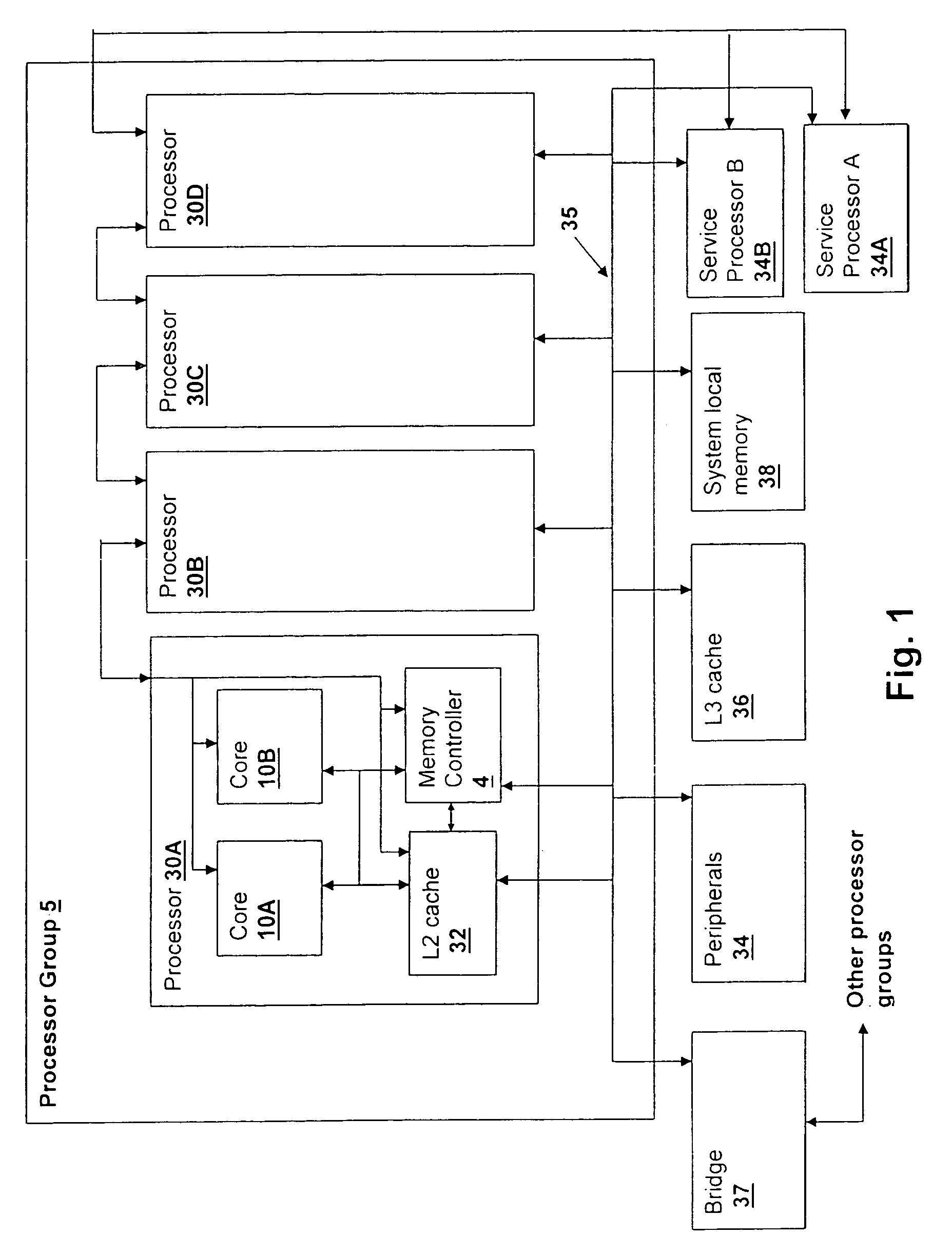
[0016]With reference now to the figures, and in particular with reference to FIG. 1, there is depicted a block diagram of a system in accordance with an embodiment of the present invention. The system includes a processor group 5 that may be connected to other processor groups via a bridge 37 forming a super-scalar processor. Processor group 5 is connected to an L3 cache unit 36 system local memory 38 and various peripherals 34, as well as to two service processors 34A and 34B. Service processors provide fault supervision, startup assistance and test capability to processor group 5 and may have their own interconnect paths to other processor groups as well as connecting all of processors 30A–D.

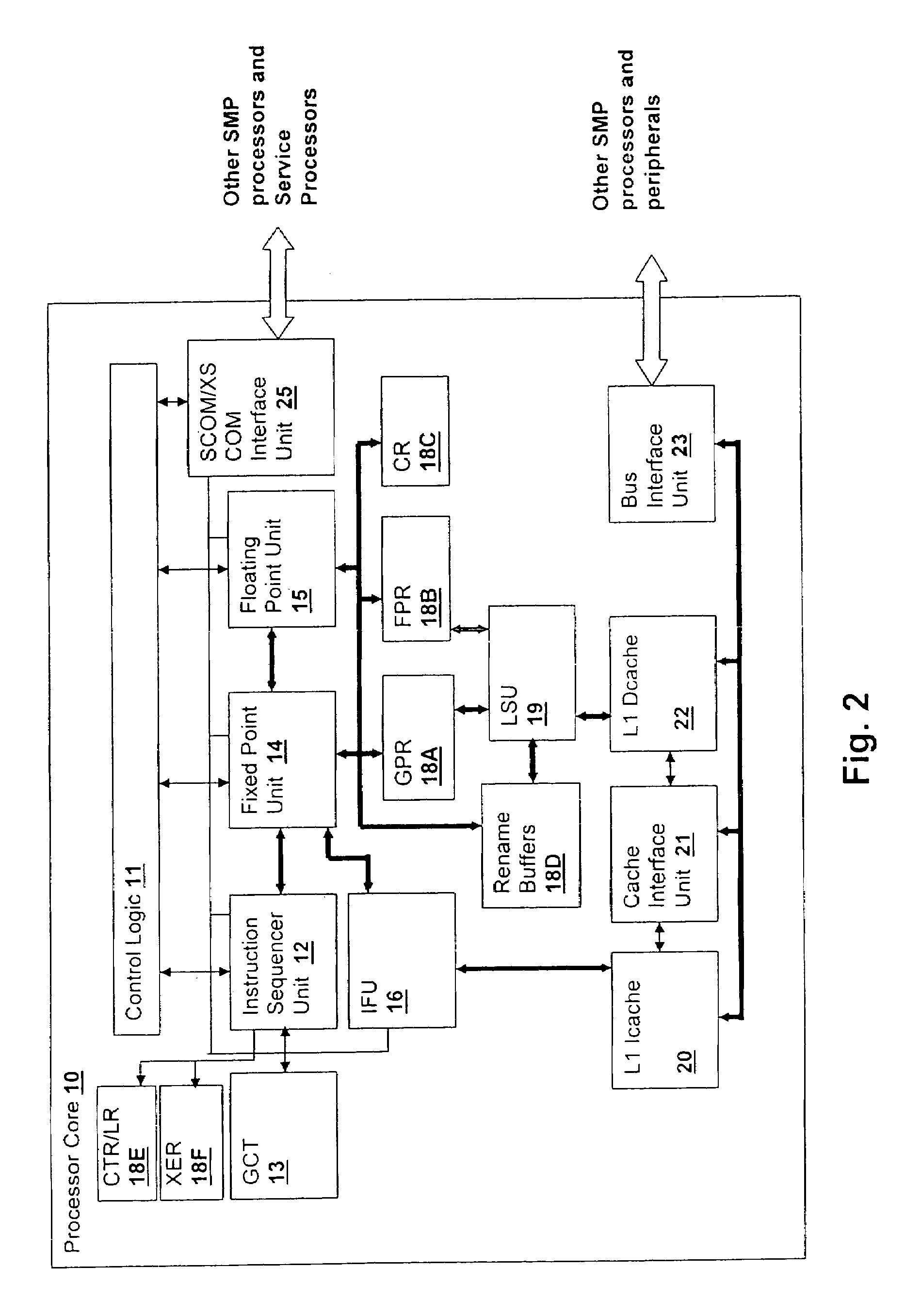
[0017]Within processor group 5 are a plurality of processors 30A–D, generally fabricated in a single unit and including a plurality of processor cores 10A and 10B coupled to an L2 cache 32 and a memory controller 4. Cores 10A and 10B provide instruction execution and operation on data values f...


PUM


Abstract

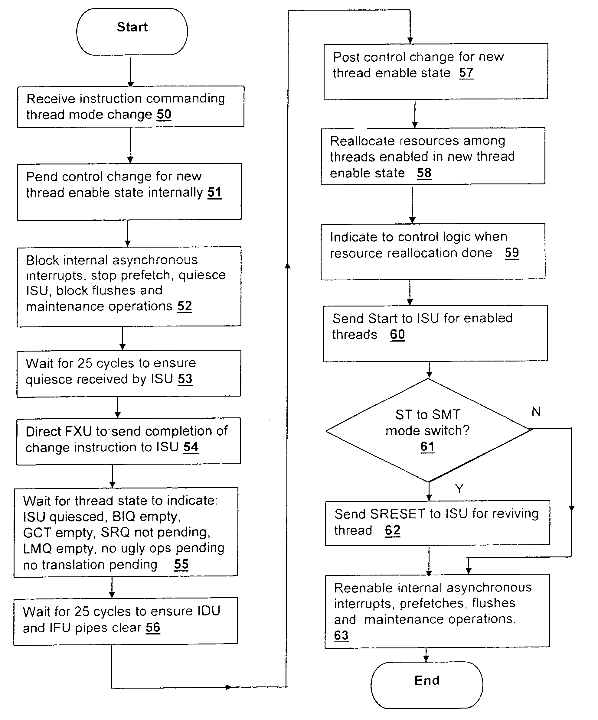
A method and logical apparatus for switching between single-threaded and multi-threaded execution states within a simultaneous multi-threaded (SMT) processor provides a mechanism for switching between single-threaded and multi-threaded execution. The processor receives an instruction specifying a transition from a single-threaded to a multi-threaded mode or vice-versa and halts execution of all threads executing on the processor. Internal control logic controls a sequence of events that ends instruction prefetching, dispatch of new instructions, interrupt processing and maintenance operations and waits for operation of the processor to complete for instructions that are in process. Then, the logic determines one or more threads to start in conformity with a thread enable state specifying the enable state of multiple threads and reallocates various resources, dividing them between threads if multiple threads are specified for further execution (multi-threaded mode) or allocating substantially all of the resources to a single thread if further execution is specified as single-threaded mode. The processor then starts execution of the remaining enabled threads.

Description

CROSS-REFERENCE TO RELATED APPLICATIONS[0001]The present application is related to co-pending U.S. patent application Ser. No. 10 / 422,649 entitled “METHOD AND LOGICAL APPARATUS FOR MANAGING RESOURCE REDISTRIBUTION IN A SIMULTANEOUS MULTI-THREADED (SMT) PROCESSOR”, U.S. patent application Ser. No. 10 / 422,651 entitled “METHOD AND LOGICAL APPARATUS FOR RENAME REGISTER REALLOCATION IN A SIMULTANEOUS MULTI-THREADED (SMT) PROCESSOR”, and U.S. patent application Ser. No. 10 / 422,682 entitled “DYNAMIC SWITCHING OF MULTITHREADED PROCESSOR BETWEEN SINGLE THREADED AND SIMULTANEOUS MULTITHREADED MODES”, filed concurrently with this application. The specifications of the above-referenced patent applications are incorporated herein by reference.BACKGROUND OF THE INVENTION[0002]1. Technical Field[0003]The present invention relates generally to processors and computing systems, and more particularly, to a simultaneous multi-threaded (SMT) processor.[0004]2. Description of the Related Art[0005]Presen...

Claims


Application Information

Patent Timeline
Patent Type & Authority Patents(United States)
IPC IPC(8): G06F15/00G06F15/76G06F7/38G06F9/00G06F9/44G06F9/48
CPCG06F9/485
Inventor BURKY, WILLIAM ELTONFLOYD, MICHAEL STEPHENKALLA, RONALD NICKSINHAROY, BALARAM
Owner INT BUSINESS MASCH CORP
Learn More