Post processor for three-dimensional objects

a three-dimensional object and post processing technology, applied in the field of solid deposition modeling, can solve the problems of shortening the time to develop prototype parts, affecting the effect of gravitational forces, and reducing the number of parts produced in rapid manufacturing processes, so as to achieve the effect of removing support materials and low cos

Active Publication Date: 2006-10-03
3D SYST INC
View PDF10 Cites 52 Cited by
  • Summary
  • Abstract
  • Description
  • Claims
  • Application Information

AI Technical Summary

Benefits of technology

[0018]It is an advantage of the present invention that the post processing apparatus is low cost and effective in removing support material from a three-dimensional object formed of a different build material without harming or damaging the object.
[0019]These and other aspects, features, and advantages are obtained in the post processing apparatus of the present invention to remove support material from an three-dimensional object formed from a different build material by selective deposition modeling by using a heated main chamber into which are pumped molten heat transfer media from separate storage reservoirs. The three-dimensional object is formed from a first heat transfer material, preferably a curable phase change composition, and the support structure is formed from a second heat transfer medium, preferably a non-curable phase change composition. The post processing apparatus stores the heat transfer medium in two heated storage reservoirs. Paraffin is a preferred heat transfer medium.

Problems solved by technology

For instance, SFF technologies dramatically shorten the time to develop prototype parts and can produce limited numbers of parts in rapid manufacturing processes.
However, one of the most fundamental problems associated with SDM processes is the adverse effect resulting from gravitational forces that act on a part during the build process.
However, all methods have their drawbacks.
However, the application of applied force to crack or crumble away the support material from the object has limitations, such as marring or damaging the three-dimensional object during support removal or breaking off entirely of delicate features.
Additionally it is difficult, and sometimes impossible, to remove the support material for certain geometric configurations, such as in deep cavities or pockets.
However, it is problematic with this approach that the solvent eventually becomes saturated with removed support material and must be disposed of, and then replaced with fresh solvent.
Additionally, unpleasant and potentially unhealthful odors are produced by the evaporation of the solvent.
Thus, implementing this approach may not be user friendly or cost effective.
None of the prior approaches provided a simple and low cost apparatus to effect reliable removal of support structure.

Method used


Image

  • Post processor for three-dimensional objects
  • Post processor for three-dimensional objects
  • Post processor for three-dimensional objects

Examples


Embodiment Construction

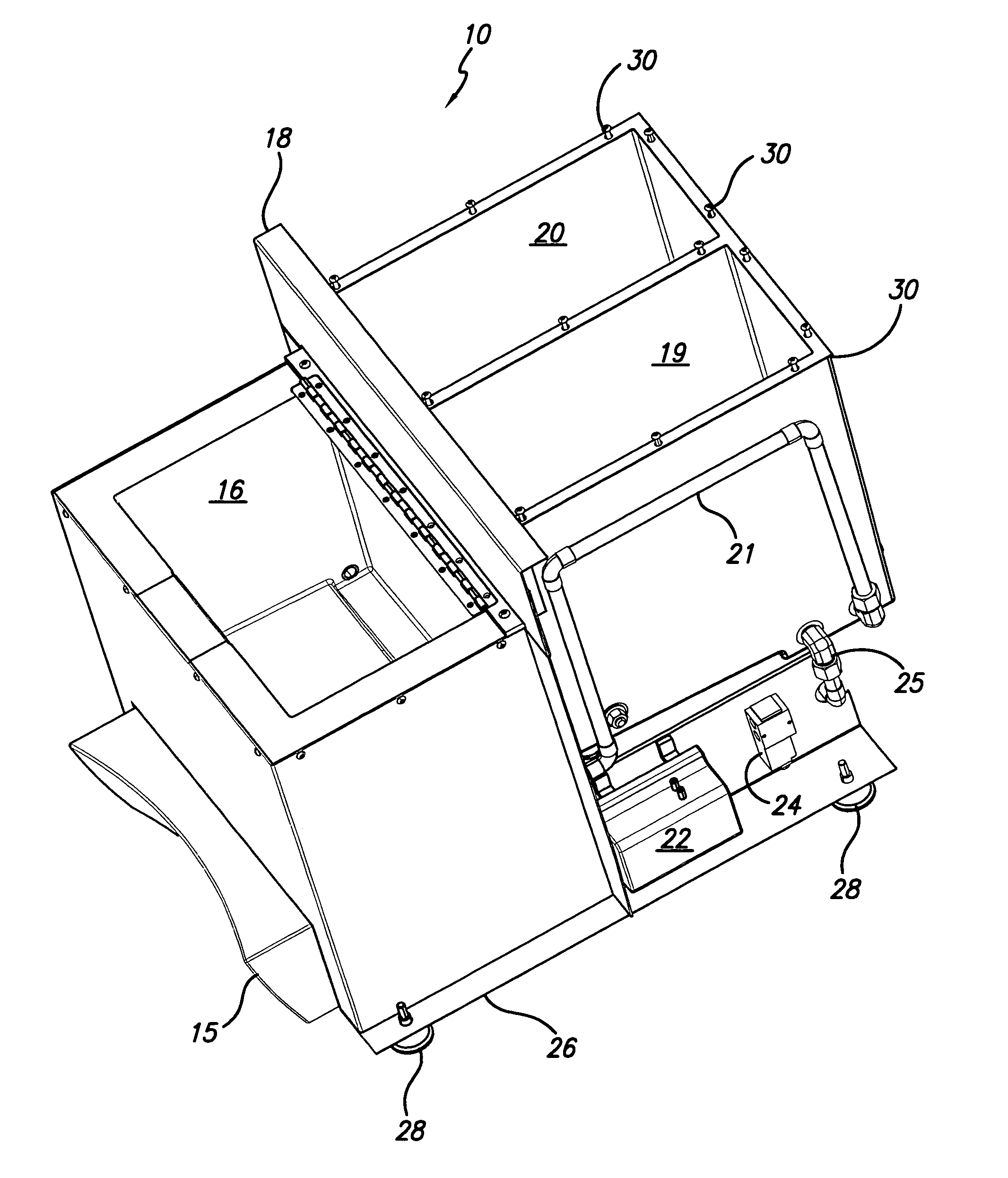
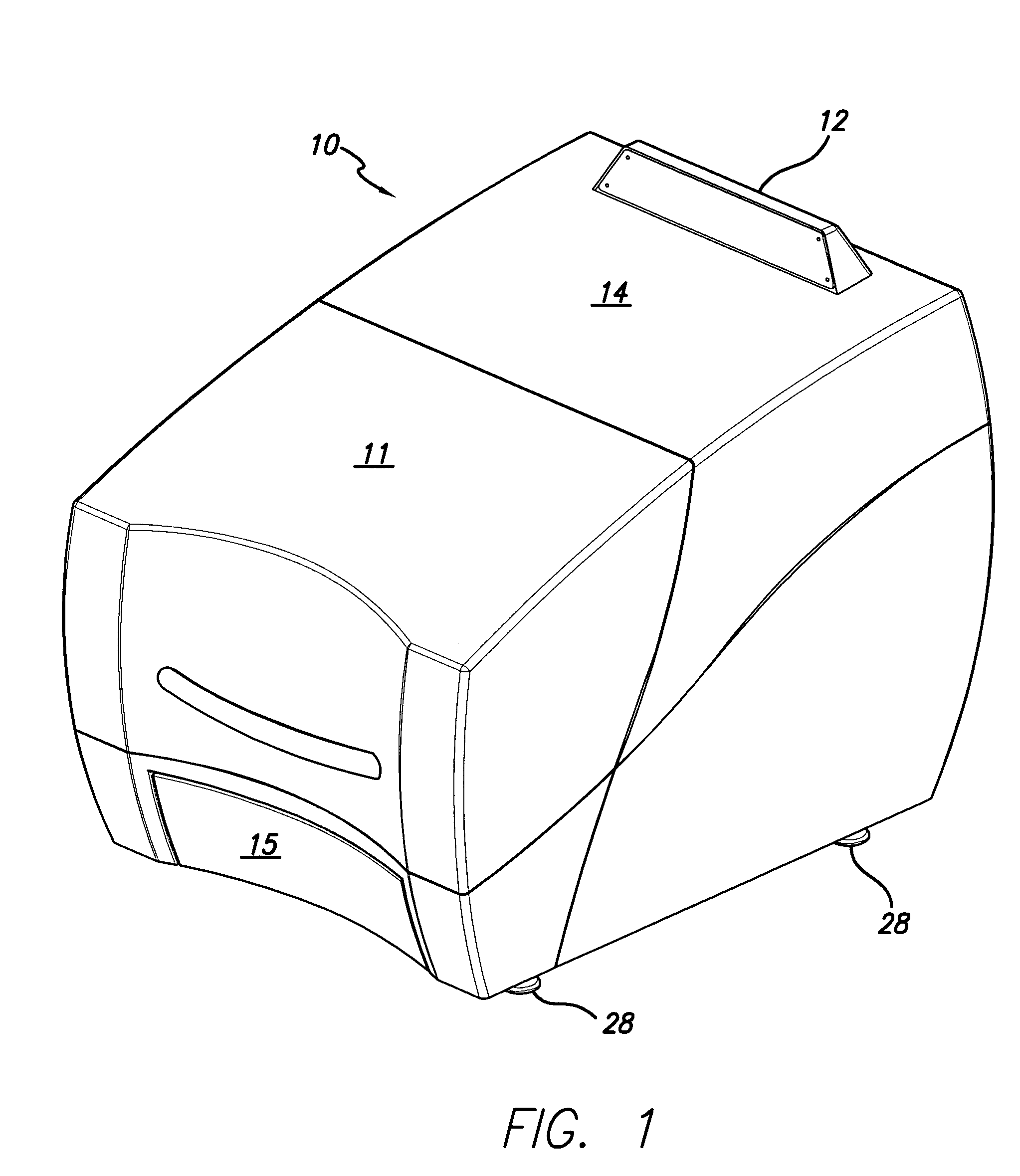
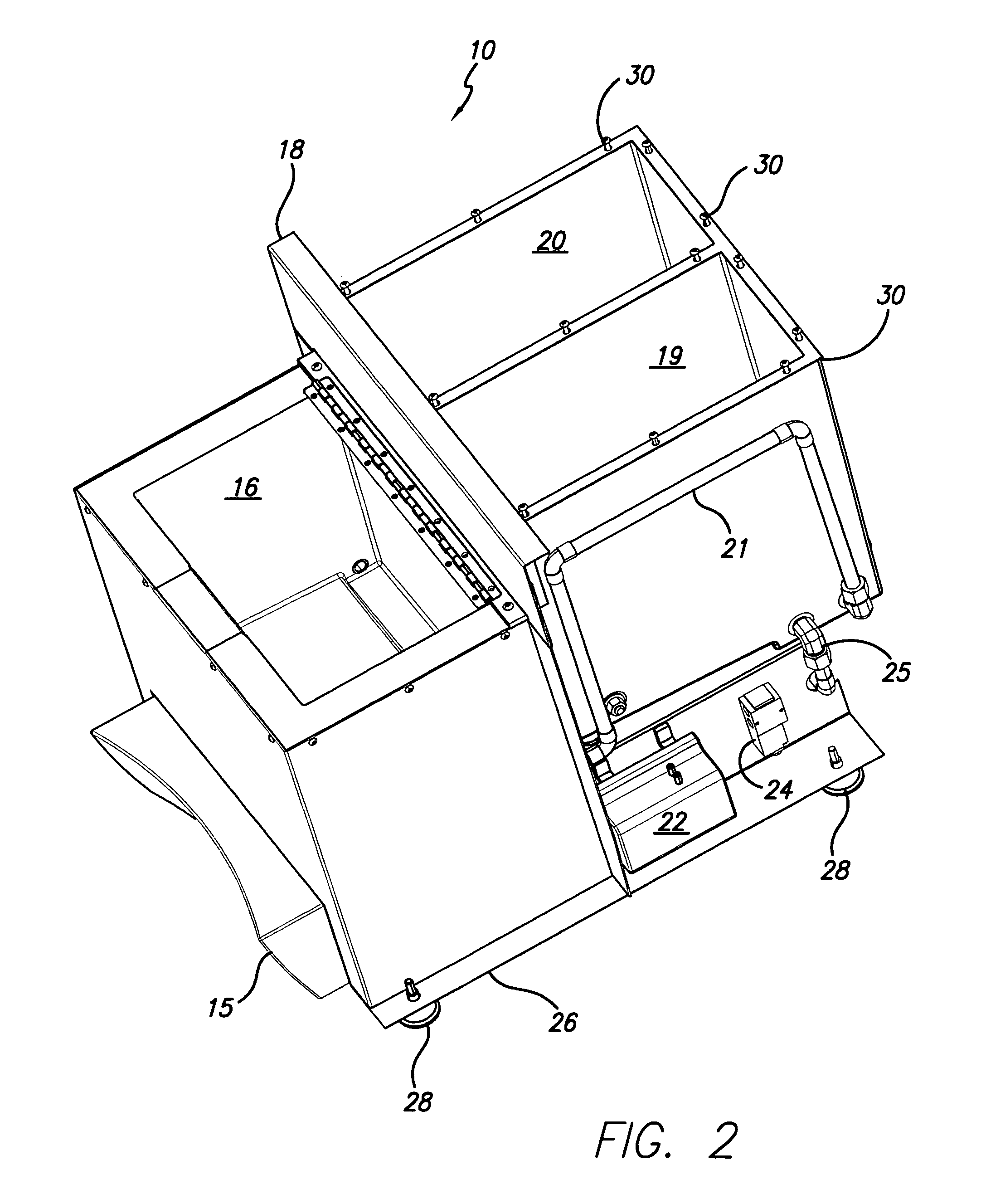
[0024]A post processing apparatus is indicated generally by the numeral 10 in FIG. 1. The apparatus 10 has a hinged access cover 11 over a main chamber 16, see briefly FIG. 2, and a removable access panel 16 to the first and second storage reservoirs 19 and 20, again see briefly FIG. 2. A control panel 12 is mounted to panel 14 and provides digital temperature displays and process cycle pads (not shown) to monitor and control the support material removal process from three-dimensional objects positioned within the main chamber 16. An overflow and waste collection receptacle 15 is removably mounted to the apparatus 10. Apparatus 10 is mounted on a base frame 26, best seen in FIGS. 2 and 3, and base supports or legs 28.

[0025]As seen in FIG. 2 the main chamber 16 has a hinged cover 18 that serves to retain heat in the chamber 16 during the support material removal process and permit easy access to the chamber. The chamber 16 is formed from aluminum and is heated with blanket type of he...


PUM

PropertyMeasurementUnit
length of timeaaaaaaaaaa
viscosityaaaaaaaaaa
freezing pointaaaaaaaaaa

Abstract

A post processing apparatus for automated removal of support material from a three-dimensional objected formed from a build material by selective deposition modeling is provided. The apparatus includes a heated main chamber into which is placed the three-dimensional object with the support material attached and first and second liquid heat transfer medium storage reservoirs. The storage reservoirs reversibly provide liquid heat transfer medium to the main chamber to immerse the three-dimensional object and the attached support material for desired periods of time to meltingly separate the support material from the object.

Description

BACKGROUND OF THE INVENTION[0001]1. Field of the Invention[0002]The invention relates in general to solid deposition modeling, and in particular to an apparatus for post processing three-dimensional objects produced by such a modeling technique to remove a non-curable phase change support material from a three-dimensional object formed from a curable phase change build material.[0003]2. Description of the Prior Art[0004]During the past two decades several new technologies have been developed for the rapid creation of models, prototypes, and parts for limited run manufacturing. These new technologies are generally called Solid Freeform Fabrication techniques, and are herein referred to as “SFF”. SFF techniques include stereolithography, selective deposition modeling, laminated object manufacturing, selective phase area deposition, multi-phase jet solidification, ballistic particle manufacturing, fused deposition modeling, particle deposition, laser sintering, and the like. Complex pa...

Claims


Application Information

Patent Timeline
Patent Type & Authority Patents(United States)
IPC IPC(8): B28B17/00B29C35/00
CPCB29C67/0092B29C67/0096B29C64/40B29C64/35B33Y40/20
Inventor FONG, JON JODYSOLIZ, RAYMOND M.
Owner 3D SYST INC
Why Eureka
Try Eureka