Eureka AIR delivers breakthrough ideas for toughest innovation challenges, trusted by R&D personnel around the world.

Combustor drain valve

a technology of drain valve and valve body, which is applied in the direction of valve operating means/release devices, turbine/propulsion fuel valves, machines/engines, etc., can solve the problems of false start of the turbine, inability to properly drain the drain valve, and often left unusable liquid fuel systems for long periods, etc., to minimize the adverse effects of contaminants

Active Publication Date: 2007-01-02
JANSENS AIRCRAFT SYST CONTROLS
View PDF13 Cites 11 Cited by
  • Summary
  • Abstract
  • Description
  • Claims
  • Application Information

AI Technical Summary

Benefits of technology

[0012]The present invention is a valve system for draining the combustion can(s) of a gas turbine engine to a drain collector, particularly after a false start. The valve system is arranged to provide for straight through flow of the drained fuel through the valve, while minimizing the adverse effects of contaminants on the sealing features of the valve. The valve is preferably normally open and actuated closed to seal off the combustion can from the drain during normal operation. After a false start of the engine, the valve is returned to open so that the unspent fuel can pass straight through the valve to the drain.
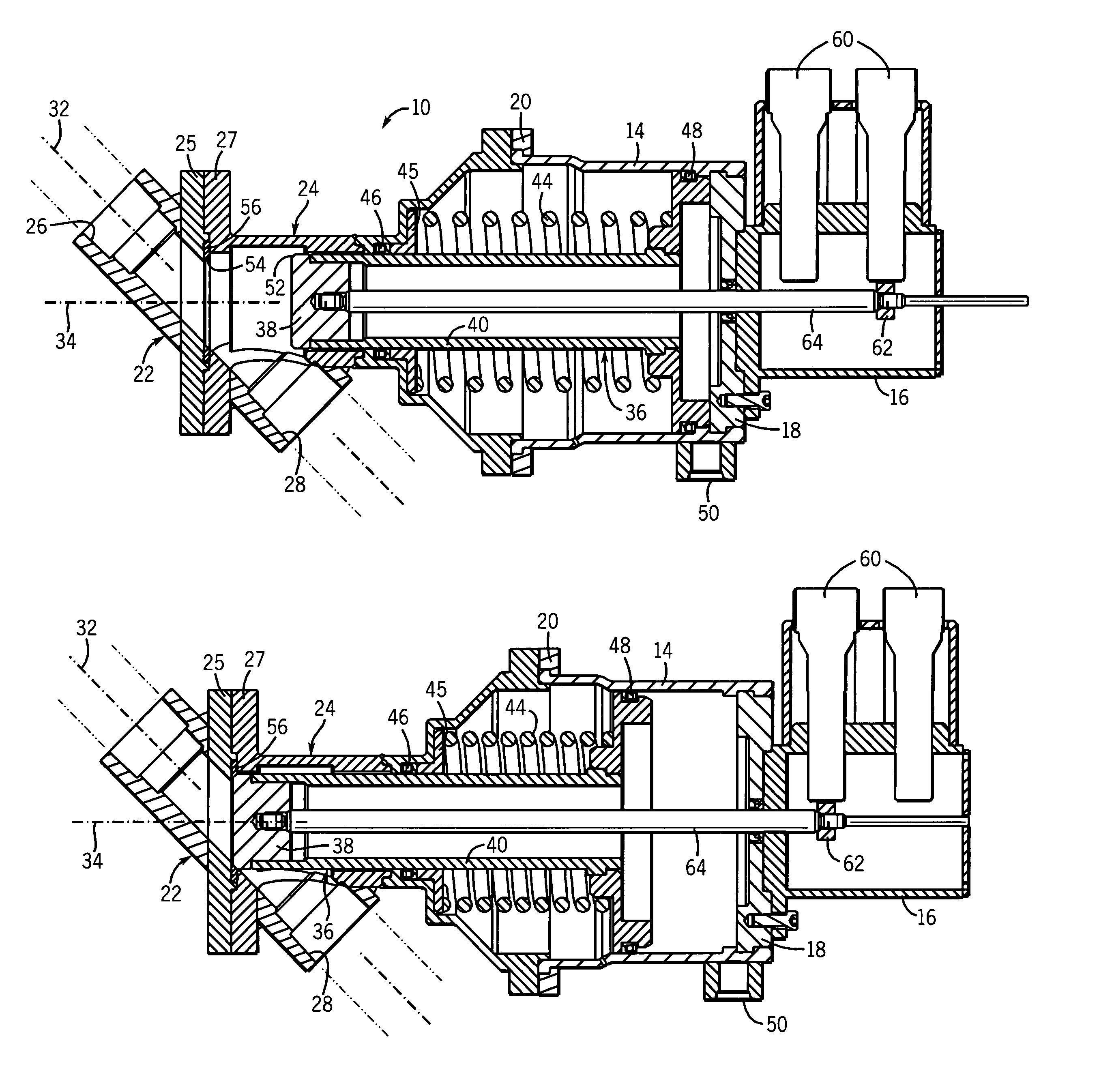
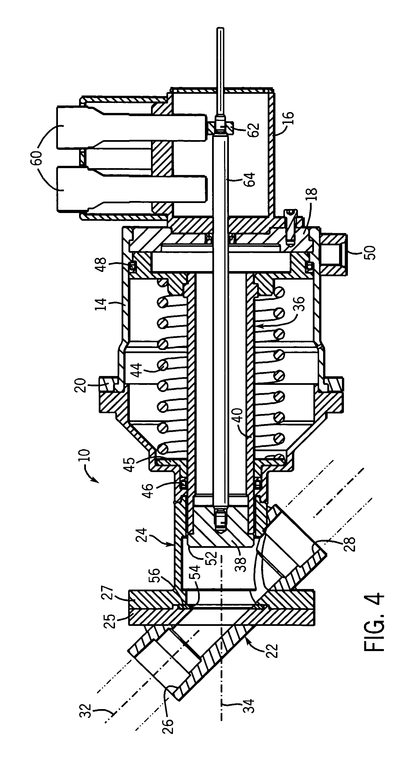
[0014]In another aspect, the invention is a drain valve having a valve housing with a pilot air inlet in communication with an air chamber and a drain passageway isolated from the air chamber and in communication between the combustion area and the drain collector. A piston has a valve and an enlarged head disposed in the air chamber of the piston housing. The piston is movable along a piston axis by application of pilot air into the air chamber acting against the piston head to seat the valve in the drain passageway at an oblique angle relative to the drain passageway and close off communication between the combustion area and the drain collector.
[0017]The valve of the present invention is thus designed for use in the extreme pressure and temperature environment of turbine engines. The oblique angular arrangement of the drain passageway and the axis of valve movement allows the drain passageway to follow a straight path through the valve and permits the valve to move straight into and out of the drain passageway when seating and unseating. This allows for straight through flow of the drained fuel with minimal pressure drop. It also allows a poppet type valve to be used to seal the drain passageway with minimal susceptibility to contamination or coking at the sealing surfaces.

Problems solved by technology

Since they ordinarily run on natural gas, the liquid fuel system is often left unused for long periods.
The heat and pressure associated with combustion of the gaseous fuel can cause “coking”, which occurs when the volatile components of the fuel are driven off by heat such that only a tarry deposit remains.
Among other things, the coke deposits can build up on the liquid fuel burners and / or inhibit proper conduit of the liquid fuel when the engine is returned to fuel mode.
When this happens at ignition, the combustion can fail causing a false start of the turbine.
This false start can leave unspent liquid fuel in the combustor(s).
Conventional valves have several disadvantages particularly with regard to high pressure drops and resisting the effects of contamination.
This change in direction of the flow presents at least two distinct problems, namely, it causes a higher pressure drop across the valve and presents locations for the liquid fuel to collect, particularly given that the drain flow is usually not under pressure.
Since the collected fuel is still in a high heat environment, it can cause a safety concern if combined with air, and it also can lead to coke deposits on the valve.
However, it is still susceptible to other adverse effects of contamination.
In particular, contaminants and coking deposits can arise on the non-sealing surface of the ball valve during operation (when the valve closes the drain).
This in turn reduces the efficiency of the engine.

Method used


Image

  • Combustor drain valve
  • Combustor drain valve
  • Combustor drain valve

Examples


Embodiment Construction

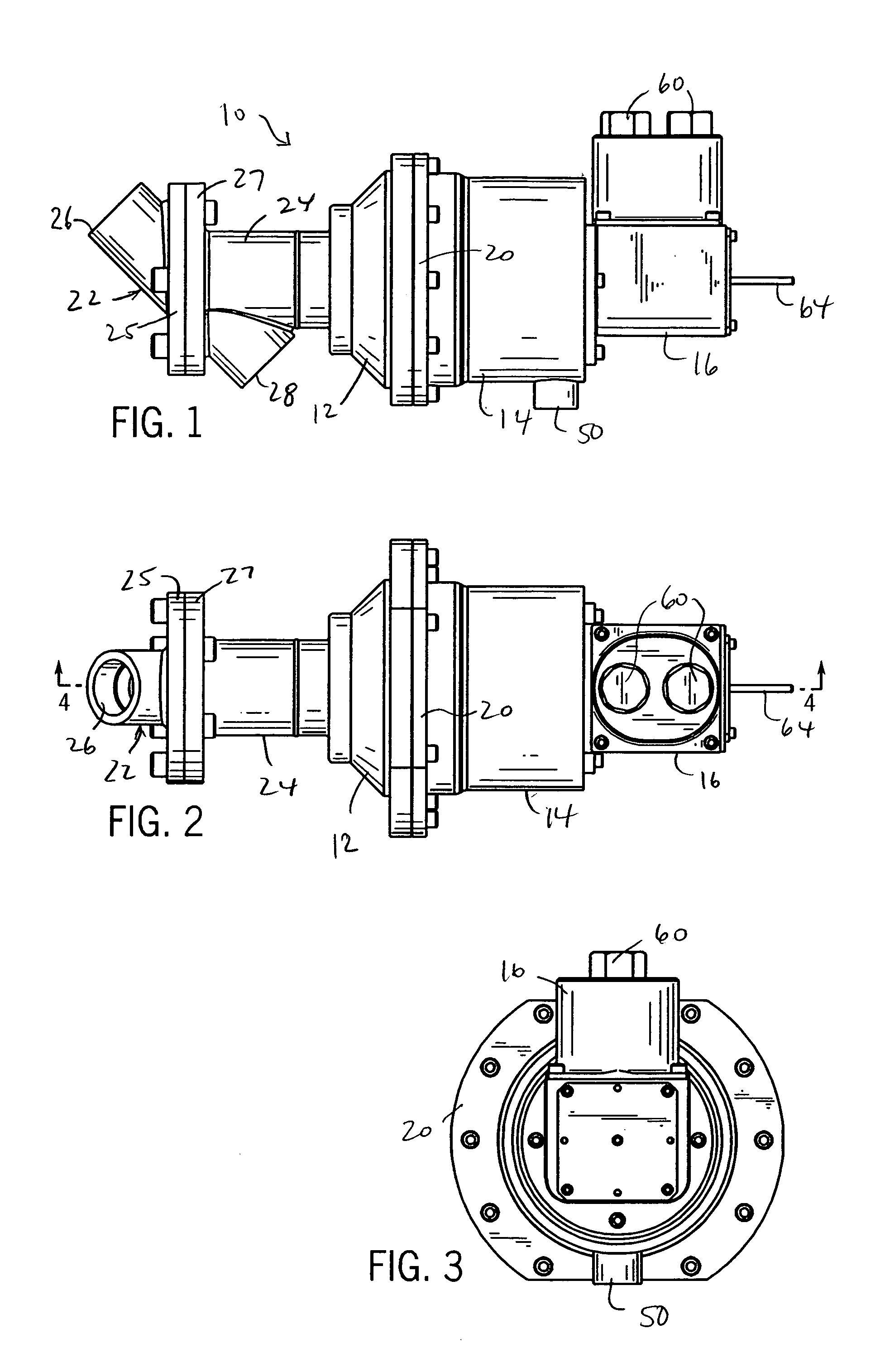
[0025]Referring to FIGS. 1–3 of the drawings, a combustor drain valve 10 of the present invention includes a body with a main housing 12, an actuator housing 14 and a position feedback housing 16. The body can be constructed of one or more separate sections joined together as needed. In the preferred form shown, the actuator housing 14 has an end cap 18 (see FIG. 4) welded to an end to which the position feedback housing 16 bolts. A retainer ring 20 is bolted in place to secure the other end of the actuator housing 14 to the main housing 12.

[0026]As shown in FIGS. 1 and 4, the main housing 12 is in part formed of two sections 22 and 24 bolted together at respective flanges 25 and 27. These two sections 22 and 24 define respective inlet 26 and outlet 28 sections of a drain passageway 30. The inlet 26 and outlet 28 have open ends that are designed to accept fittings or other couplers for joining the valve to lines leading from the combustion can(s) of a turbine engine and a drain coll...


PUM


Abstract

A system for draining fuel from the combustion chamber of a gas turbine engine in the event of a false start includes associated passageways and a straight through flow pilot air actuated poppet valve. The valve is normally open and actuated by the pilot air to close off the combustion chamber from the drain. A return spring biases the valve to open upon release of pilot air pressure acting on the valve. The valve housing has a piston section with a pilot air chamber and a section defining the passageways for the drain. The drain passageway extends along a straight path at an oblique angle to a piston axis along which a piston actuator moves in response to the return spring and / or the pilot air pressure. The valve also includes a position feedback system for detecting the state of the valve.

Description

CROSS-REFERENCE TO RELATED APPLICATION[0001]This application claims benefit to U.S. provisional application Ser. No. 60 / 487,026 filed Jul. 14, 2003.STATEMENT OF FEDERALLY SPONSORED RESEARCH OR DEVELOPMENT[0002]Not applicable.BACKGROUND OF THE INVENTION[0003]1. Technical Field[0004]The present invention relates to valves, and in particular, to valves for draining the combustion area of turbine engines.[0005]2. Description of the Related Art[0006]Gas turbine engines are commonly used in power generation and propulsion applications. Gas turbine engines have a set of rotating turbine blades to compress air leading to one or more combustors into which fuel is injected and ignited. Fuel is delivered through metering orifices to burners in the combustors under pressure through a fuel line. Combustion of the fuel turns a downstream set of blades, used for energy extraction or propulsion, and which can be used to drive the compressor blades.[0007]Gas turbine engines typically burn gaseous fu...

Claims


Application Information

Patent Timeline
Patent Type & Authority Patents(United States)
IPC IPC(8): F02G3/00F02C7/232
CPCF02C7/232F05D2260/85F05D2260/602
Inventor JANSEN, HARVEY B.SHIELDS, DAVID K.
Owner JANSENS AIRCRAFT SYST CONTROLS
Why Eureka
Eureka Blog
Learn More