Method for installing an ignition system, and ignition system

a technology of installation method and installation method, which is applied in the direction of electric fuzes, instruments, lighting and heating apparatus, etc., can solve the problems of inability to accurately allocate a inconvenient installation of the intended application, and inability to accurately determine etc., to achieve substantially facilitate the installation of the ignition system, accurate the geographical position of the ignition device, and accurately allocate the delay time to the respective ignition devi

Inactive Publication Date: 2007-01-02
ORICA EXPLOSIVES TECH PTY LTD
View PDF5 Cites 10 Cited by
  • Summary
  • Abstract
  • Description
  • Claims
  • Application Information

AI Technical Summary

Benefits of technology

[0009]For use in exploration and in the extraction of raw materials an autonomous system is used according to the invention. A transmitter (feed transmitter for correction data) is installed in each quarry, opencast mine or exploration field and its geographical position is accurately measured. These data are used in order to correct the GPS co-ordinates. With this method it is possible to determine a position to an accuracy of 20 cm. By coupling the drilling plan data it is also conceivable additionally to increase the accuracy by for example comparing the distances of the boreholes from one another specified in the drilling plan with the co-ordinates of the boreholes determined by means of the expanded GPS system (DEGPS) and then comparing the resulting distances from one another.
[0011]If the ignition devices provided for a blasting operation are freely programmable as regards their delay time, then according to the invention only the respective identification codes and the geographical co-ordinates determined by means of the GPS system are needed in order individually to prepare a blasting plan with the aid of a computer loaded with suitable software. The accurate maintenance of the sequence of ignition devices with preset delay times is no longer necessary when the devices are installed in the boreholes, since each ignition device can be identified in the blasting plan and can therefore also individually be accessed and thus also programmed. For this reason ignition devices can be reprogrammed as regards the delay time or can be withdrawn completely from an already installed ignition system without having to intervene physically. This is advantageous if, due to unforeseen circumstances, for example due to a stripping device that has been left behind, a region has to be withdrawn from the envisaged blasting operation.
[0012]By using the global positioning system expanded with a feed transmitter, it is possible according to the invention to identify accurately the geographical position of ignition devices in an ignition system anywhere in the world and thereby accurately allocate a delay time to the respective ignition device. It is therefore advantageous to combine the satellite-supported navigation system, the GPS receiver, together with the electronics for collecting and processing the ignition device data and transmitting the latter to the logger, in one unit, the ignition device data and position transmitting unit, whereby the installation of an ignition system is substantially facilitated.

Problems solved by technology

The measurement accuracy is however of an order of magnitude of only about 30 m. Such an inaccuracy is of course unacceptable for the intended application.
Such transmitters are not available in sparsely populated regions of the world, for example Australia, Canada or Siberia, which means that the use of the GPS system consequently leads to unacceptable deviations from the actual position.

Method used


Image

  • Method for installing an ignition system, and ignition system
  • Method for installing an ignition system, and ignition system
  • Method for installing an ignition system, and ignition system

Examples


Embodiment Construction

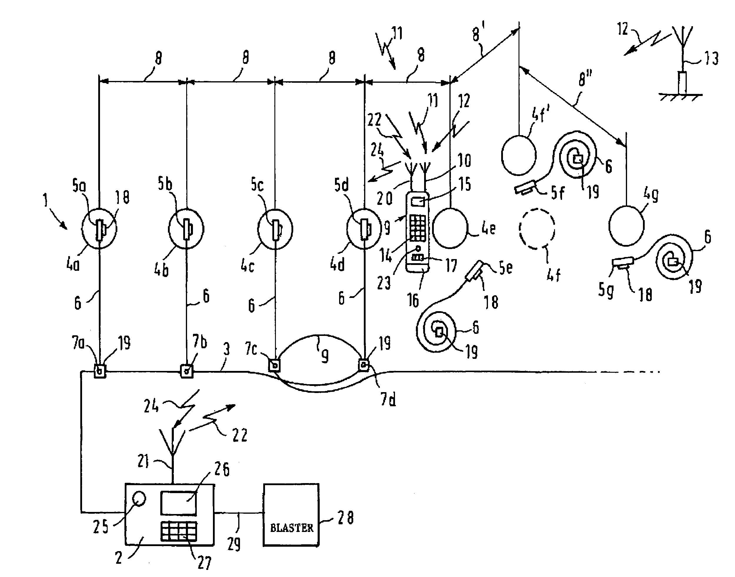
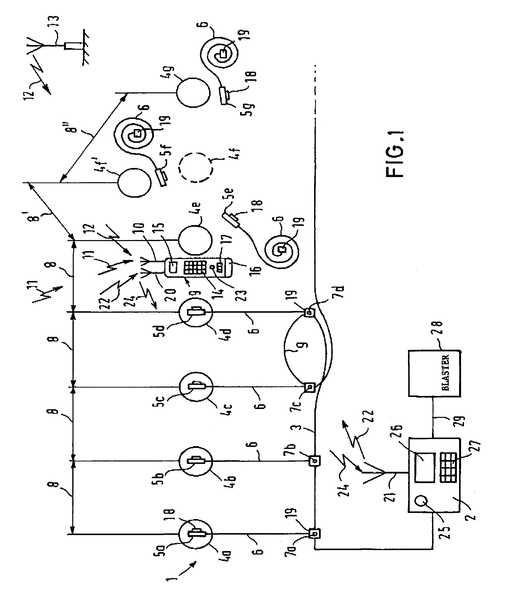
[0026]FIG. 1 shows an ignition system according to the invention, identified overall by the reference numeral 1. A bus line 3 has been laid from a data reading and storage unit, i.e. a logger 2, along the boreholes 4a to 4g. The arrangement illustrated in FIG. 1 may be regarded as a section of an ignition system having a substantially larger number of boreholes. An ignition device 5a to 5g is associated with each of the illustrated boreholes 4a to 4g. An ignition line 6 is already connected to the ignition devices 5a to 5g; the line 6 is in turn connected to the bus line 3 once connection has already been made to the connection points 7a to 7d, for example inductively or by electrical contact.

[0027]The boreholes 4a and 4g should be at a specified distance 8 from one another, which is entered on a drilling plan. The distance 8 of the boreholes from one another is thus known. As a rule the distance 8 of the boreholes from one another is constant if for example there are a large number...


PUM


Abstract

When an ignition system is installed, the spatial position of an ignition device (5a to 5g) in relation to the surrounding, its geographical position, is as yet not determined. The user is required to exercise extreme caution in order to ensure that the ignition devices (5a to 5g) connect to the ignition system (1) in accordance with a predetermined blasting plan. A specially trained person must therefore systematically carry out the sequential connection (compulsory sequence) of each ignition device (5a to 5g) to the bus line (3) of the ignition system. i.e. logging. The person connecting the ignition devices must execute the ignition of device programming operation in all kinds of conditions, in open country, with utmost caution. This represents a considerable time delay for a blast. If one ignition device is overlooked during logging, the already entered data have to be reprogrammed, which costs time. The invention provides that the geographical position (4a to 4e, 4f′, 4e) of an ignition device (5a to 5g) is determined using a satellite-assisted navigation system (GPS) (10) and this position is conveyed to the logger (2).

Description

BACKGROUND OF THE INVENTION[0001]The present invention relates to a method for installing an ignition system, and the ignition system.[0002]An ignition system consists of a data reading and storage unit, a so-called logger, to which a plurality of ignition devices (fuses) are connected via a bus line, which ignition devices are ignited in a predetermined chronological order on the basis of an ignition command from an ignition unit connected upstream of the logger or from a triggering device, a so-called blaster. The bus line may in addition to the transmission of the signal also serve to supply energy to the ignition devices, in particular to charge up the ignition capacitors. Such ignition systems are used in the opencast mining of, mineral resources, for example ores and coal, and in the rock and earth industry.[0003]Ignition systems are known that use ignition devices that have for example an identification number allocated during the course of manufacture or that have a barcode ...

Claims


Application Information

Patent Timeline
Patent Type & Authority Patents(United States)
IPC IPC(8): F42B3/26F42C17/04F42D1/05F42D1/055
CPCF42D1/055F42D1/05
Inventor AEBI, WALTERPETZOLD, JANSCHAFER, HEINZZEMLA, ANDREAS
Owner ORICA EXPLOSIVES TECH PTY LTD
Why Eureka
Try Eureka