Throttle device

a technology of throttle valves and valves, which is applied in the direction of mechanical devices, engine controllers, machines/engines, etc., can solve the problems of motor upsizing and electric power consumption, and achieve the effect of preventing the synchronization deviation of each throttle valv

Inactive Publication Date: 2007-01-02
MIKUNI CORP
View PDF8 Cites 10 Cited by
  • Summary
  • Abstract
  • Description
  • Claims
  • Application Information

AI Technical Summary

Benefits of technology

[0008]With this structure, for a normal operation, when the throttle shaft is rotated by the first drive means, the throttle valve performs an open-close operation while rotating between the rest position at the closing side and the full open position. On the other hand, in the state of emergency etc. such as malfunction of the first drive means, the second drive means is activated; either by a driver's switch operation or automatically in the case of an electromagnetic type, and by a driver's hand operation in the case of a hand driven type. Then, the throttle shaft rotates, and returns the throttle valve to the rest position. In this manner, since the second drive means is not activated and does not exert return force during a normal operation, an open-close operation can be performed smoothly.
[0016]With this structure, even if the return operation is performed while the drive force of the first drive means is exerted, torsion of the throttle shaft can be prevented because the urging force of the return operation is exerted to compete in the vicinity of the drive force. Particularly, in the case that the throttle shaft is supporting a plurality of throttle valves, synchronization deviation of each throttle valve can be prevented.

Problems solved by technology

Therefore, the electric power consumption is increased, and the motor is upsized.

Method used


Image

  • Throttle device
  • Throttle device
  • Throttle device

Examples


Embodiment Construction

[0021]The embodiments of the present invention are explained in the following with reference to the attached drawings.

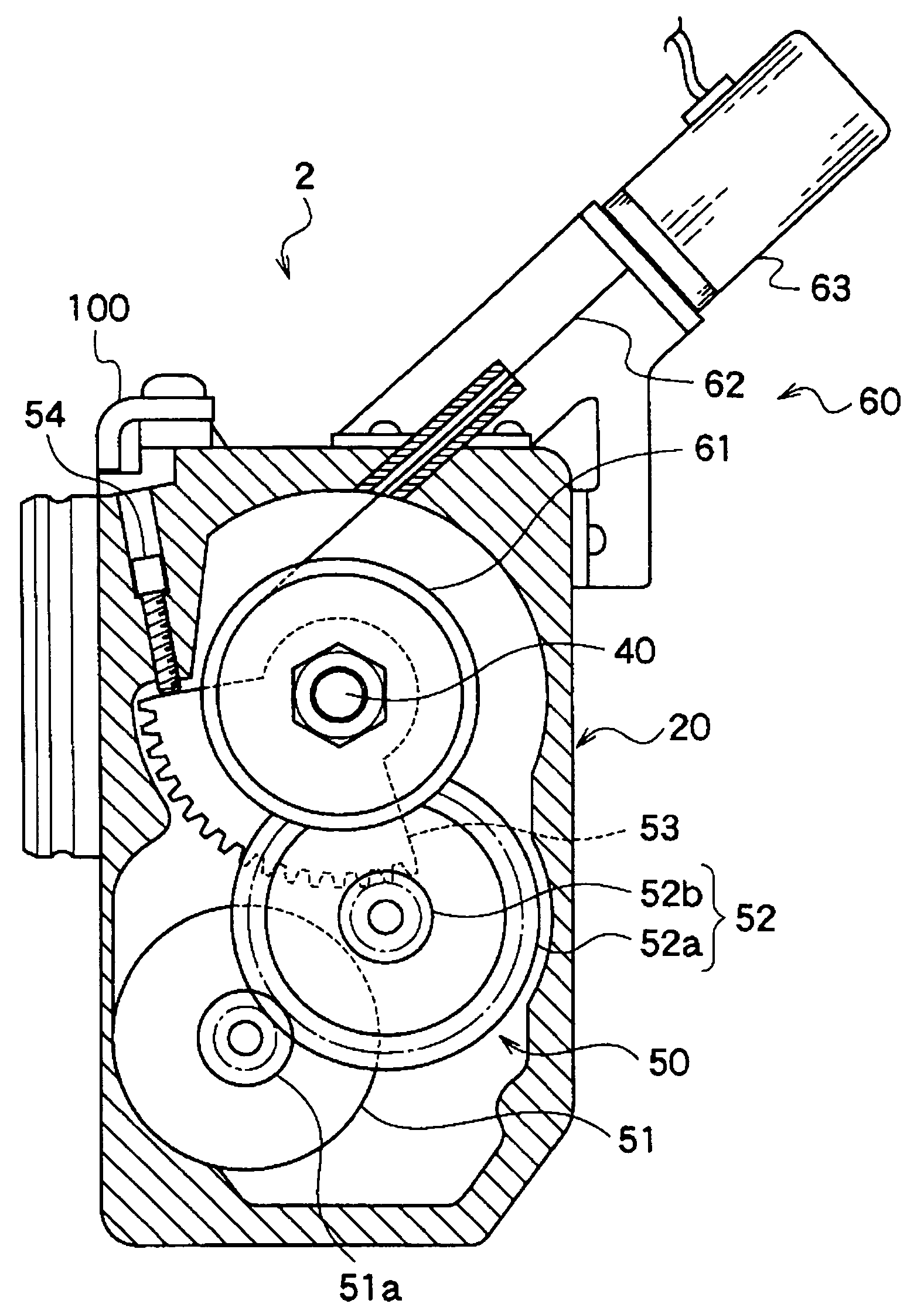
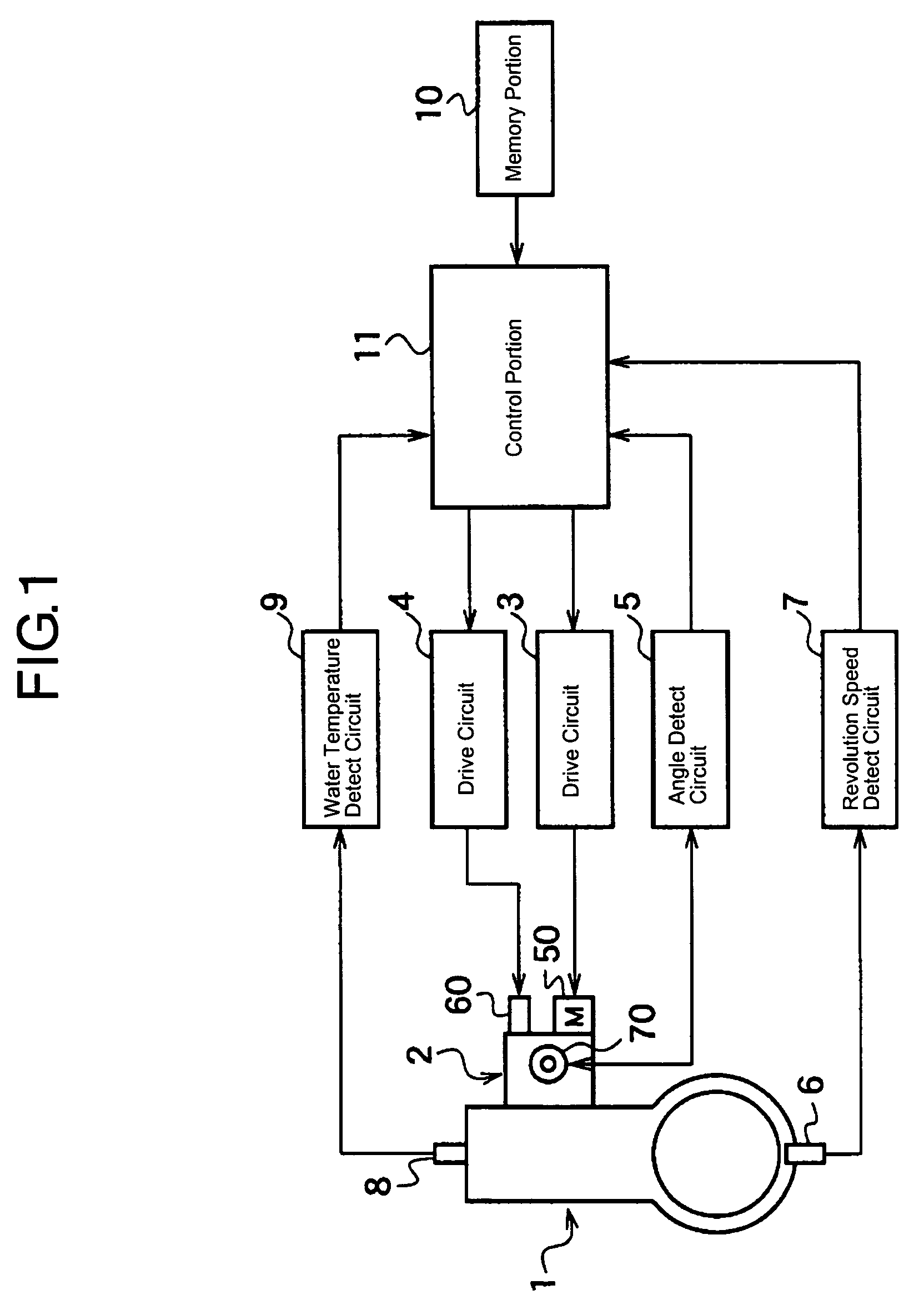
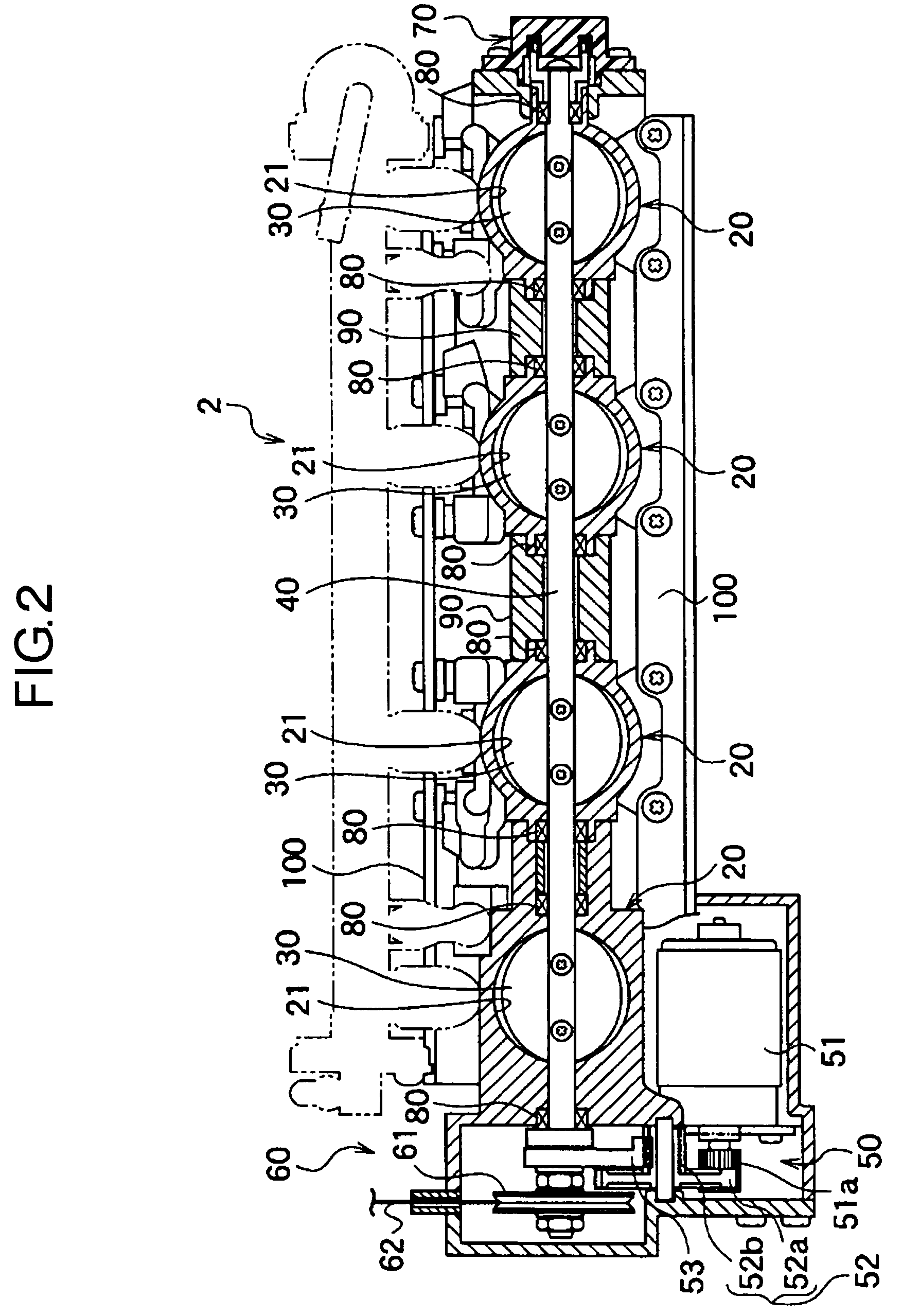
[0022]FIGS. 1 through 3 show an embodiment of a throttle apparatus of the present invention. FIG. 1 is a block diagram showing a control system. FIG. 2 is a sectional view of the throttle apparatus. FIG. 3 is a side view of an electromagnetic drive means etc.

[0023]As shown in FIG. 1, the control system comprises an engine 1, a four-barrel throttle apparatus 2 which is mounted on an intake system of the engine 1, a drive circuit 3 for driving a first drive means 50 which is disposed at the apparatus 2, a drive circuit 4 for driving a second drive means 60, an angle detect circuit 5 for processing signals from an angle detect sensor 70 which detects the angle position of a throttle valve 30 of the apparatus 2, a revolution sensor 6 and a revolution speed detect circuit 7 for detecting revolution speed of the engine 1, a water temperature sensor 8 and a water temperatur...


PUM


Abstract

With the throttle apparatus of the present invention having a throttle valve 30 disposed at an intake passage, a throttle shaft 240 to open and close the throttle valve 30, a DC motor 51 to drive the throttle shaft 40, and so on, a second drive means 60 is disposed to exert return force to the throttle shaft 40 only for returning the throttle valve 30 to the rest position. With this structure, since return force is not exerted with a normal operation, load to the DC motor 51 is decreased, and an open-close operation can be preformed smoothly. By returning the throttle valve to the rest position utilizing other means than spring force, load to the motor is decreased, and open-close operation is smoothed.

Description

TECHNICAL FIELD[0001]The present invention relates to a throttle apparatus which has a throttle valve to open and close the intake passage of an engine. More particularly, it relates to a throttle apparatus which includes a mechanism to return the throttle valve to a specific rest position.BACKGROUND ART[0002]As a conventional throttle apparatus which is applied for an engine mounted on an automobile, a wire-cum-electronic controlled type and just an electronic controlled type are known.[0003]For example, with the conventional wire-cum-electronic controlled type throttle apparatus for a six-cylinder V-type engine, the intake system has two surge tanks collecting three intake passages respectively which correspond to each cylinder and intake passages extending to the upstream side from each surge tank. By coupling two throttle valves disposed at each intake passage of the upstream side with one throttle shaft, and driving to open and close by a wire or a motor, the throttle valves ar...

Claims


Application Information

Patent Timeline
Patent Type & Authority Patents(United States)
IPC IPC(8): F02D9/10F02B61/02F02D9/02F02D11/02F02D11/04F02D11/10
CPCF02D9/02F02D9/1065F02D9/1095F02D11/04F02D11/107F02D11/02F02B61/02F02D2009/0277F02D2009/0271
Inventor HANASATO, MAKI
Owner MIKUNI CORP
Why Eureka
Try Eureka