Power converter method and apparatus having high input power factor and low harmonic distortion

a power converter and input power factor technology, applied in the direction of electric variable regulation, process and machine control, instruments, etc., can solve the problems of overheating of distribution lines, poor power factor, severe deterioration of ac supply quality, etc., to reduce the complexity of control circuits, reduce the stress of circuit components, and improve circuit reliability

Inactive Publication Date: 2007-01-02
MICROSEMI
View PDF3 Cites 95 Cited by
  • Summary
  • Abstract
  • Description
  • Claims
  • Application Information

AI Technical Summary

Benefits of technology

[0103]The present invention employs a single-stage, single-switch, input-output isolated converter configuration using a hybrid combination of forward and flyback converter topology. It uses a novel control scheme based on duty cycle control in conjunction with two discrete operating frequencies. A continuously varying operating frequency is not required, reducing the complexity of the control circuit. It results in reduced peak current stress on the circuit components leading to higher circuit reliability. Since the converter operation switches between two operating frequencies, its noise spectrum spreads out [51] making it more electromagnetic co

Problems solved by technology

While this scheme is straightforward and economical, it severely deteriorates the quality of the AC supply by drawing peak currents near the peak of the input AC voltage as shown in FIG. 1B.
This current is rich in harmonics (total harmonic distortion, THD, is very high) and results in poor power factor.
There are several major disadvantages associated with ha

Method used


Image

  • Power converter method and apparatus having high input power factor and low harmonic distortion
  • Power converter method and apparatus having high input power factor and low harmonic distortion
  • Power converter method and apparatus having high input power factor and low harmonic distortion

Examples


Embodiment Construction

The Problems To Be Solved by the Invention:

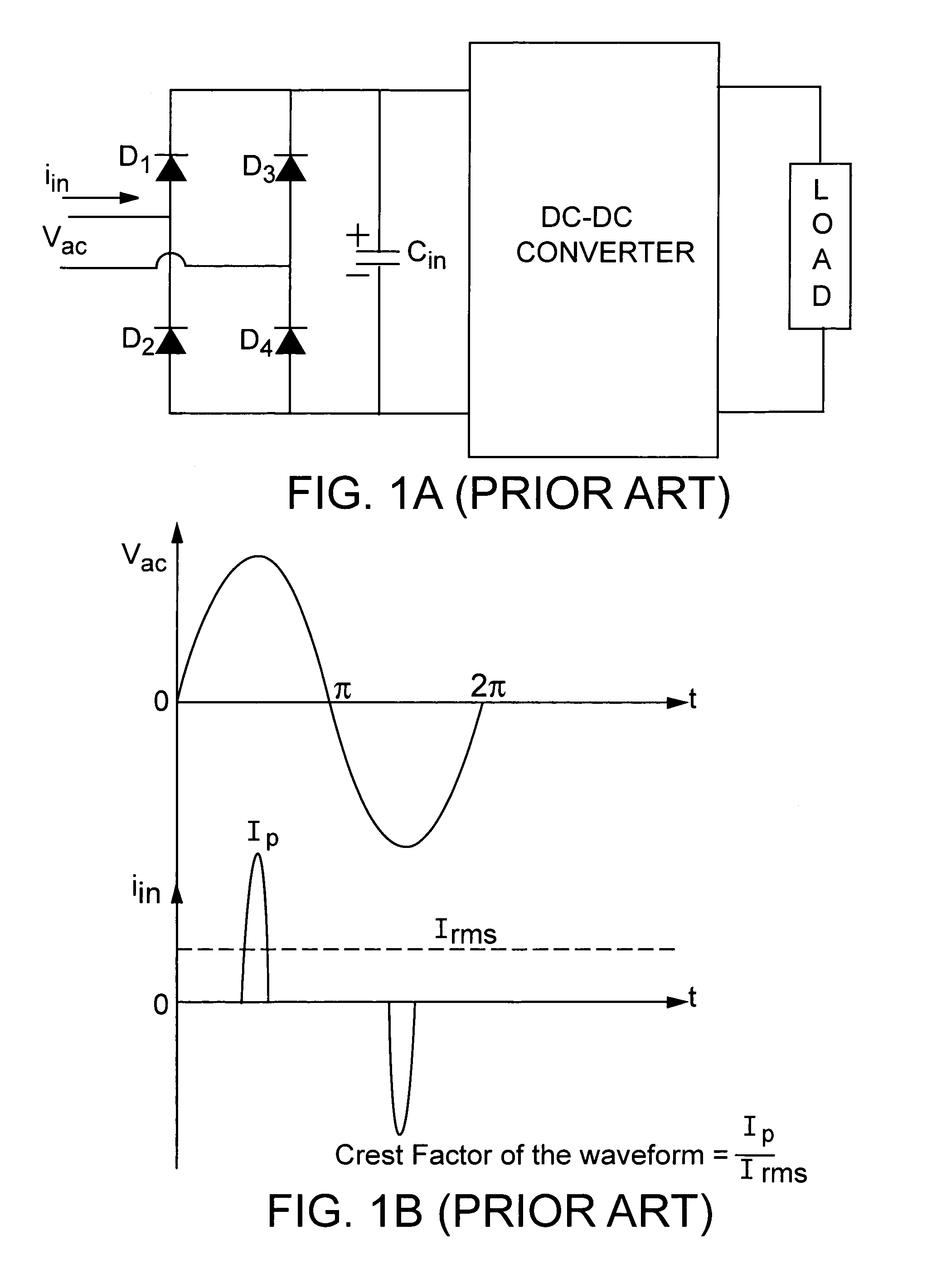
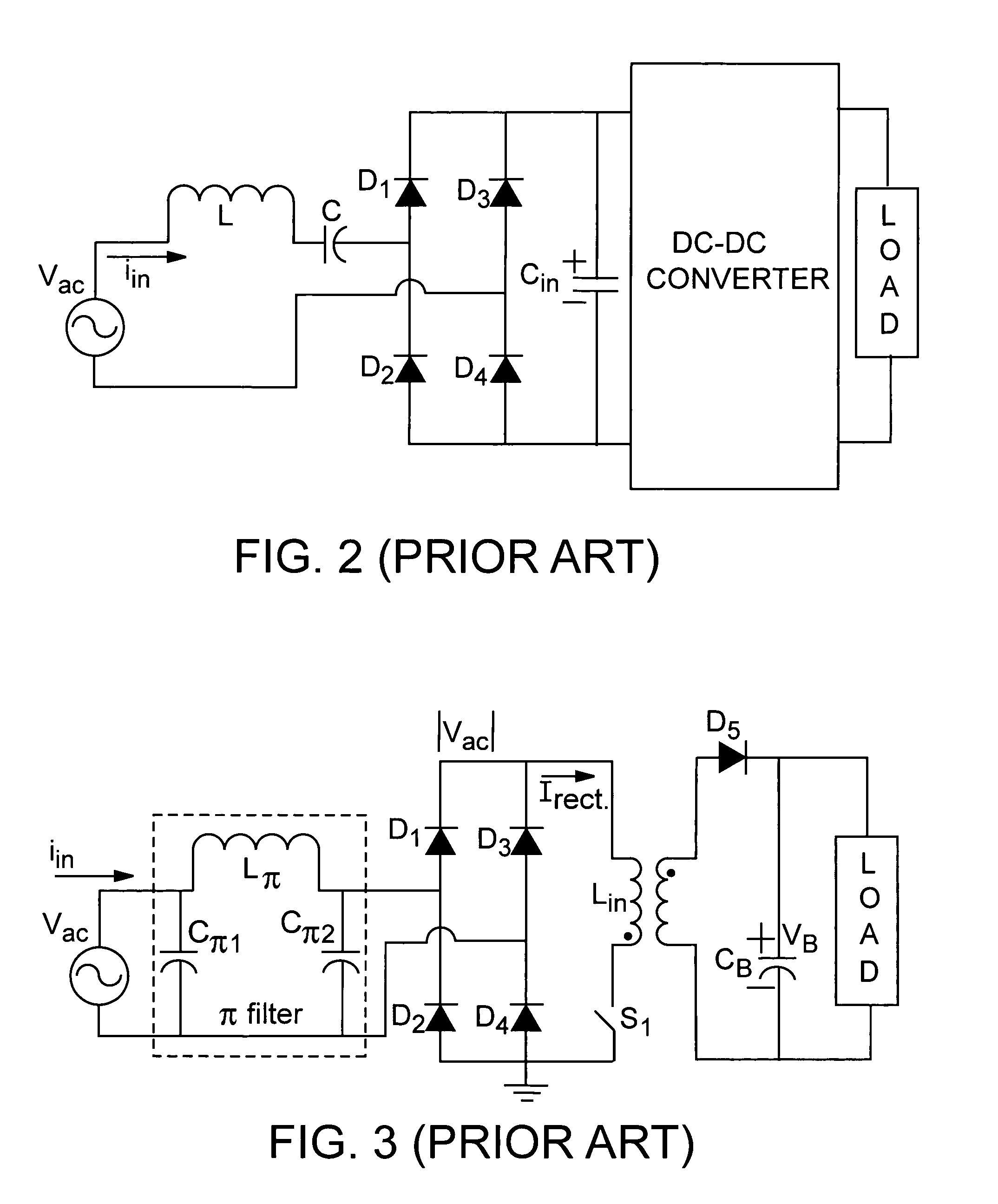
[0123]As is clear from the brief review presented in the preceding sections, the existing schemes suffer from one or more of the following drawbacks:

[0124](a) The size, weight and volume of the system is great.

[0125](b) The cost of the system is high.

[0126](c) The circuit topology (e.g. single stage, two stage etc.) is complex.

[0127](d) The control strategy is complex.

[0128](e) Output voltage regulation within the specified range is not possible.

Further, buck applications requiring 12V, 24V and 48V supplies are generally not possible.

[0129](f) The output ripple content is high.

[0130](g) The peak current stress is great on the devices and the transformer.

[0131](h) The efficiency of the converter is low.

Objectives:

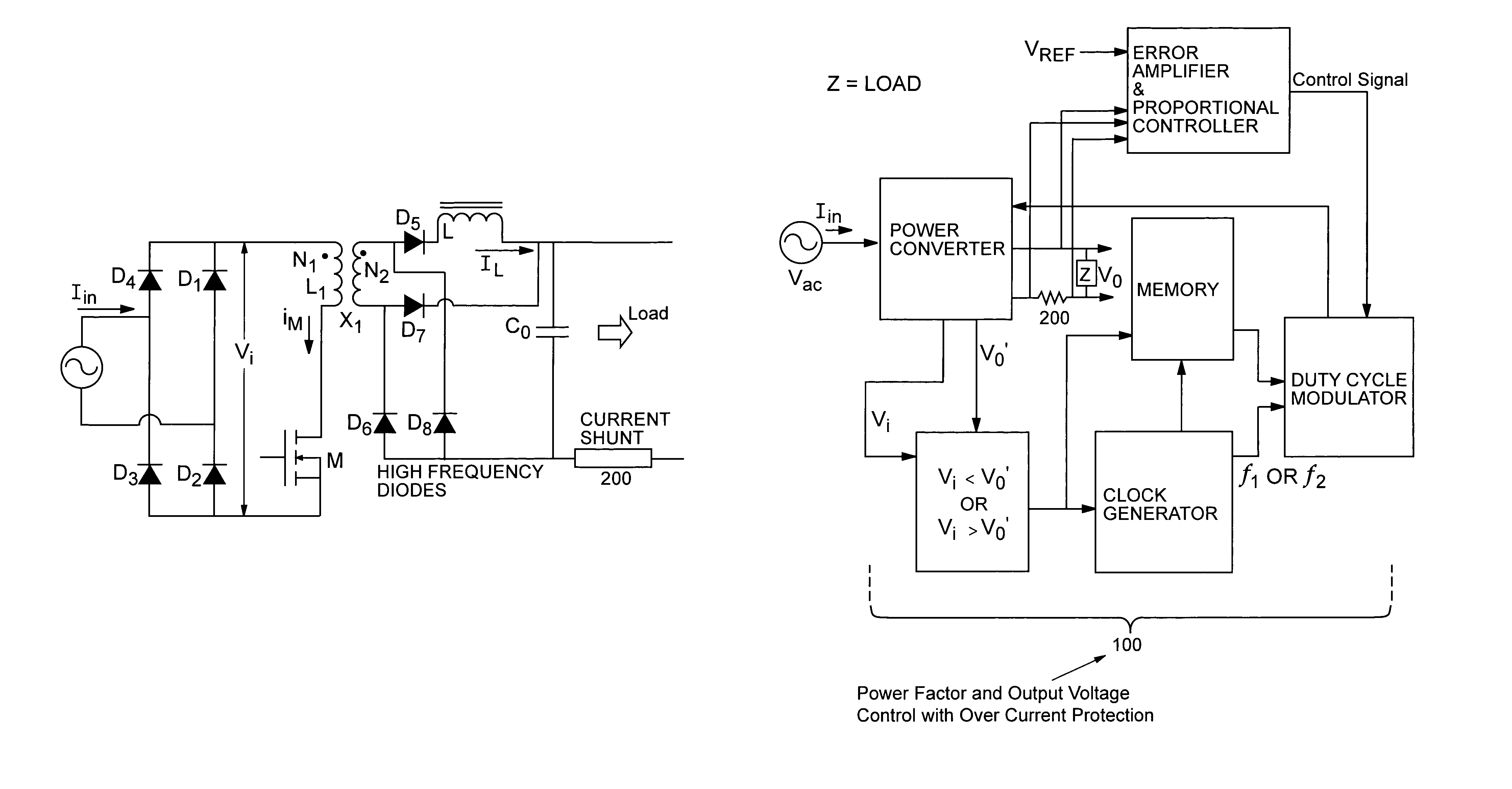
[0132]Both Single Stage and Multiple stage converters (employing one or more switches) have been extensively used as power factor correction stages in all sorts of systems. The present invention is based on the following objectives:...


PUM


Abstract

A single stage, single switch, input-output isolated converter configuration which uses a hybrid combination of forward and flyback converters is disclosed. The converter operates at a high input power factor with a regulated DC output voltage. It makes use of a novel control scheme utilizing duty cycle control at two discrete operating frequencies. Although the invention employs two frequencies, it does not use a continuous frequency variation. This configuration has the advantage of reduced peak current stresses on the components and is specifically suited for ‘buck’ applications where low DC output voltages (e.g. 24V, 48V) are needed. This configuration will be of specific interest to industries associated with battery charging and uninterruptible power supply (UPS) systems. Apart from having several competitive features compared with prior art techniques, the dual frequency operation scheme reduces the amplitude of its noise spectrum by spreading it over a wider frequency range thus making it more electromagnetic compatible.

Description

RELATED APPLICATIONS[0001]The present application claims priority from provisional U.S. Provisional Patent Application Ser. No. 60 / 420,193 entitled A SMART POWER CONVERTER MODULE FOR BUCK APPLICATIONS OPERATING AT HIGH INPUT POWER FACTOR, filed Oct. 21, 2002, the disclosure of which is incorporated herein by this reference.BACKGROUND OF THE INVENTION[0002]The present invention relates to power converter circuits for use in power supply, battery backup or uninterruptible power supply and other power conversion applications. More particularly, it relates to the implementation of an exemplary power module concept featuring high input power factor, simplicity of design, low-cost and good efficiency. The power module circuit having a single-stage and employing only a single-switch incorporates a hybrid of duty cycle and frequency control to achieve low total harmonic distortion (THD), low peak current stress on the transformer secondary circuit elements and low electromagnetic interferen...

Claims


Application Information

Patent Timeline
IPC IPC(8): G05F1/70H02M1/00H02M1/42H02M3/335
CPCH02M1/4208H02M1/425Y02B70/126H02M1/4258Y02B70/10H02M7/00H02M7/02
Inventor AGARWAL, VIVEKSUNDARSINGH, VICTOR PRINCEBONTEMPS, SERGECALMELS, ALAIN
Owner MICROSEMI
Why Eureka
Try Eureka