Multi-mode power amplifier

a power amplifier and multi-mode technology, applied in the direction of amplifier combinations, automatic tone/bandwidth control, gated amplifiers, etc., can solve the problems of power amplifiers, power amplifiers, which were optimized, and power amplifiers consuming unduly large currents at the typical lower power rang

Active Publication Date: 2007-01-02
SEMICON COMPONENTS IND LLC
View PDF2 Cites 49 Cited by
  • Summary
  • Abstract
  • Description
  • Claims
  • Application Information

AI Technical Summary

Problems solved by technology

This observation poses new design challenges for power amplifiers.
One of these challenges is that power amplifiers have to amplify the received, or input, signals in a very broad range by the same factor.
Another challenge is that power amplifiers, which were optimized for power output at the highest power-ranges consume unduly large currents at the typical lower power ranges.
Such switching elements introduce non-linearities and losses into the transmission characteristics, occupying valuable chip area and requiring supply current.

Method used


Image

  • Multi-mode power amplifier
  • Multi-mode power amplifier
  • Multi-mode power amplifier

Examples


Embodiment Construction

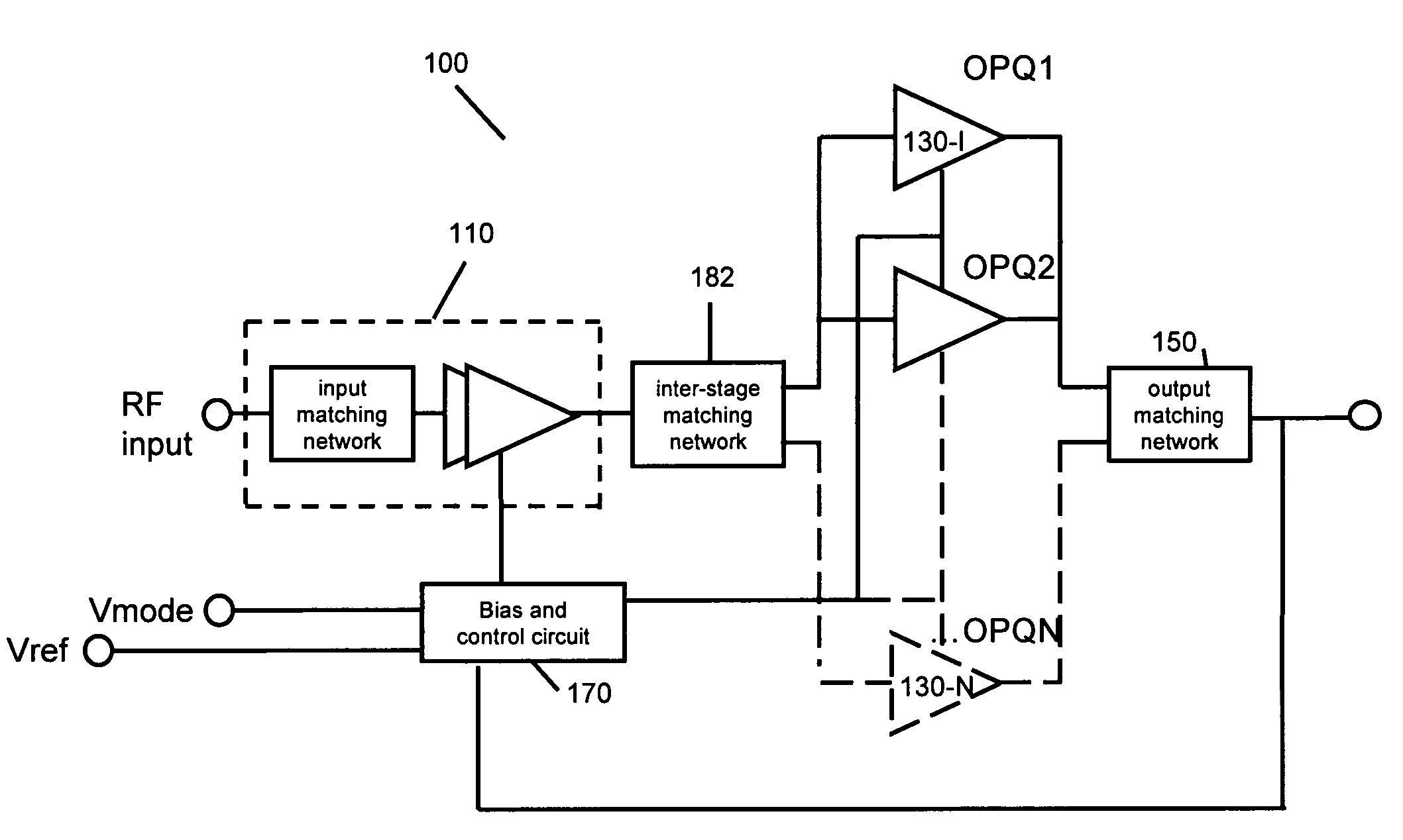
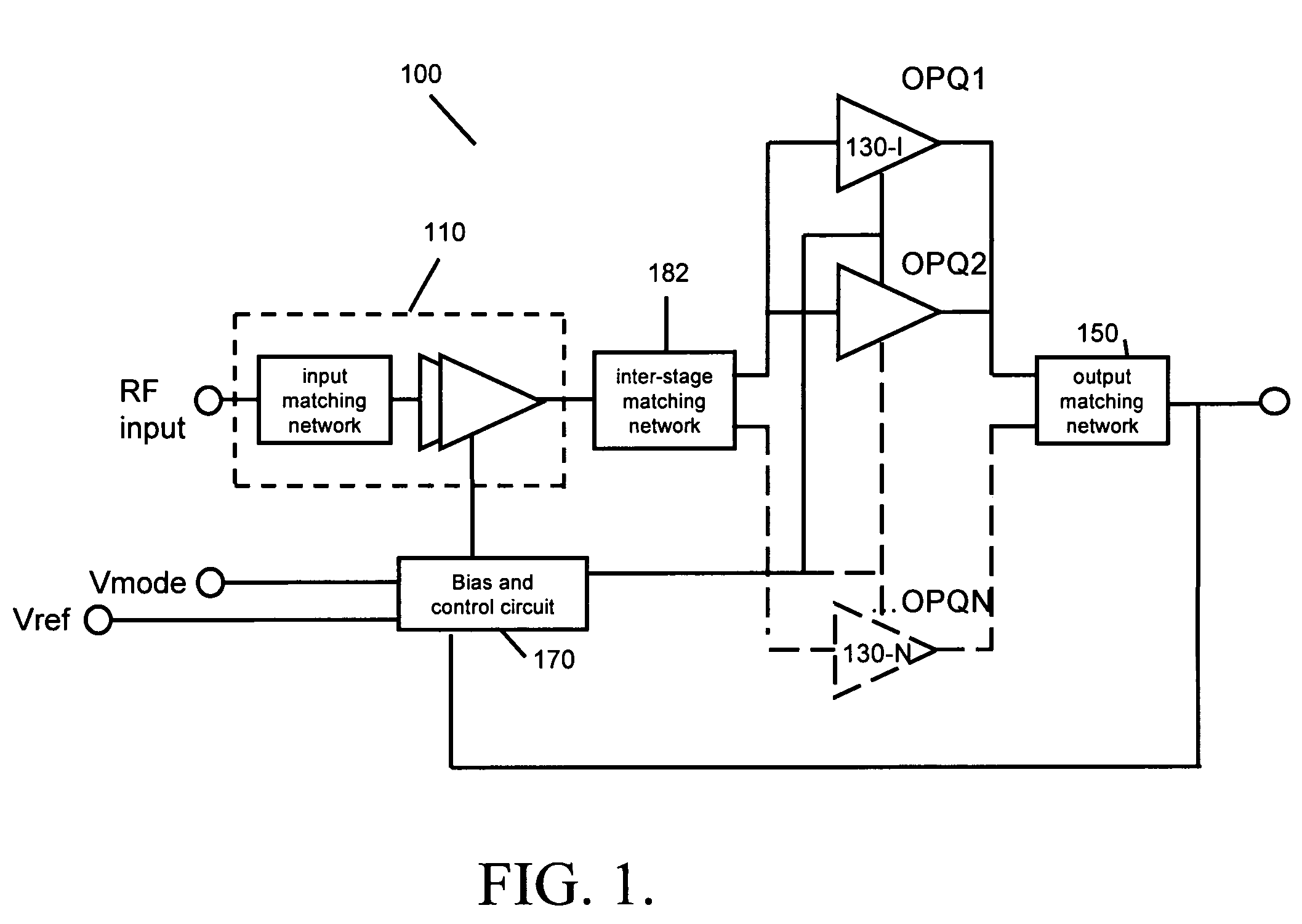
[0027]FIG. 1 illustrates a power amplifier 100 according to embodiments of the invention. Power amplifier 100 includes an input network 110, output stages 130, an output impedance matching network 150, and a bias-control network 170.

[0028]In embodiments input network 110 includes a single radio-frequency input circuit 102, coupled to it an input matching network 104, which is coupled into a shared first amplifier stage 106. As described later, shared first amplifier stage 106 is also coupled to bias-control network 170. In various applications including cell phones and other wireless systems single radio-frequency input circuit 102 receives its signal from a receiver antenna or another radio-frequency signal source.

[0029]A function of input matching network 104 is to reduce / minimize reflections of the incoming rf signal to input network 110. The input signal then enters into shared first amplifier stage 106, which may contain more than one amplifier stages within, as indicated by th...


PUM


Abstract

A power amplifier includes an input network, output stages, coupled in parallel and configured to output power optimally in corresponding power-ranges, the output stages coupled to the input network, an output impedance matching network, coupled to the output stages and not containing a switching element, and a bias-control network, coupled between the output impedance matching network, the input network, and the output stages. In some amplifiers the output impedance matching network does not contain a switching element corresponding to the output stage configured to output power in the highest range. In other amplifiers the bias-control network is configured to isolate output stages by providing a hard shut-off to transistors of the isolated output stages.

Description

BACKGROUND[0001]1. Field of Invention[0002]The present invention relates to power amplifiers and more particularly to multi-mode power amplifiers with improved linearity and reduced current consumption.[0003]2. Description of Related Art[0004]Power amplifiers are ubiquitous in modern electronics. There is a constant demand to decrease the power consumption and increase the linearity of power amplifiers in consumer electronic devices, especially portable devices. Conventional designs of power amplifiers focused on optimizing the power consumption and transmission characteristics for power outputs at the highest power-ranges.[0005]However, a remarkable observation is represented by FIG. 2. The probability density function (PDF) of the usage of portable devices, such as cell phones, reveals that most of the time these devices are used at powers nowhere near the highest power-ranges. A key reason for this fact is that cell phones are typically in close proximity to the nearest base stat...

Claims


Application Information

Patent Timeline
Patent Type & Authority Patents(United States)
IPC IPC(8): H03G5/16
CPCH03F1/0261H03F1/0277H03F3/72H03F3/211H03F1/14
Inventor BAREE, ATIQULHAU, GARYSHIROKOV, MIKHAILROCHE, JR., JAMES A.
Owner SEMICON COMPONENTS IND LLC
Why Eureka
Try Eureka