
Voltage controlled resistor and a controlling method

Inactive Publication Date: 2007-01-02
NOKIA TECHNOLOGLES OY
View PDF8 Cites 2 Cited by
  • Summary
  • Abstract
  • Description
  • Claims
  • Application Information

AI Technical Summary

Benefits of technology

[0023]By setting suitable VVR blocks to operate within certain voltage ranges of linear response and by switching off others within the same voltage range in the nonlinear response area, it is produced an operating range with a wider voltage range, as there is always some part of the entity comprising VVR blocks functioning linearly enough in said range defined by the operating parameters. Then, as a whole, a VVR according to the invention operates over a large impedance and voltage range and guarantees an advantageous dynamic range. By connecting linearly operating VVR blocks in parallel it is additionally achieved a low minimum resistance for the VVR and VVA according to the invention.

Problems solved by technology

Optimization of transmission power is important in a portable terminal, for example, because if the transmission power is too low, it may cause annoying breaks in the connection or the connection may be lost altogether.
If, on the other hand, the transmission power is too high, it may interfere with nearby devices and unnecessarily drain the power source of the portable device.
It is possible to attempt to solve the linearity problem by connecting FETs in series or using smaller FETs, but in both of these cases the minimum resistance of the VVR increases, which in practice will narrow down the dynamic range and usually causes additional losses.
The linearity gets worse when adjusting the FET from the minimum resistance state towards higher resistance values whereby nonlinearity grows detrimental.
VVRs fabricated using typical monolithic GaAs processes are not linear enough, which in practice hampers their use in the VVAs of radio devices.
Their drawback is poor linearity.
Therefore, the linearity of the VVA operation when implemented with a typical FET-based VVR, is rather poor as well.

Method used


Image

  • Voltage controlled resistor and a controlling method
  • Voltage controlled resistor and a controlling method
  • Voltage controlled resistor and a controlling method

Examples


Embodiment Construction

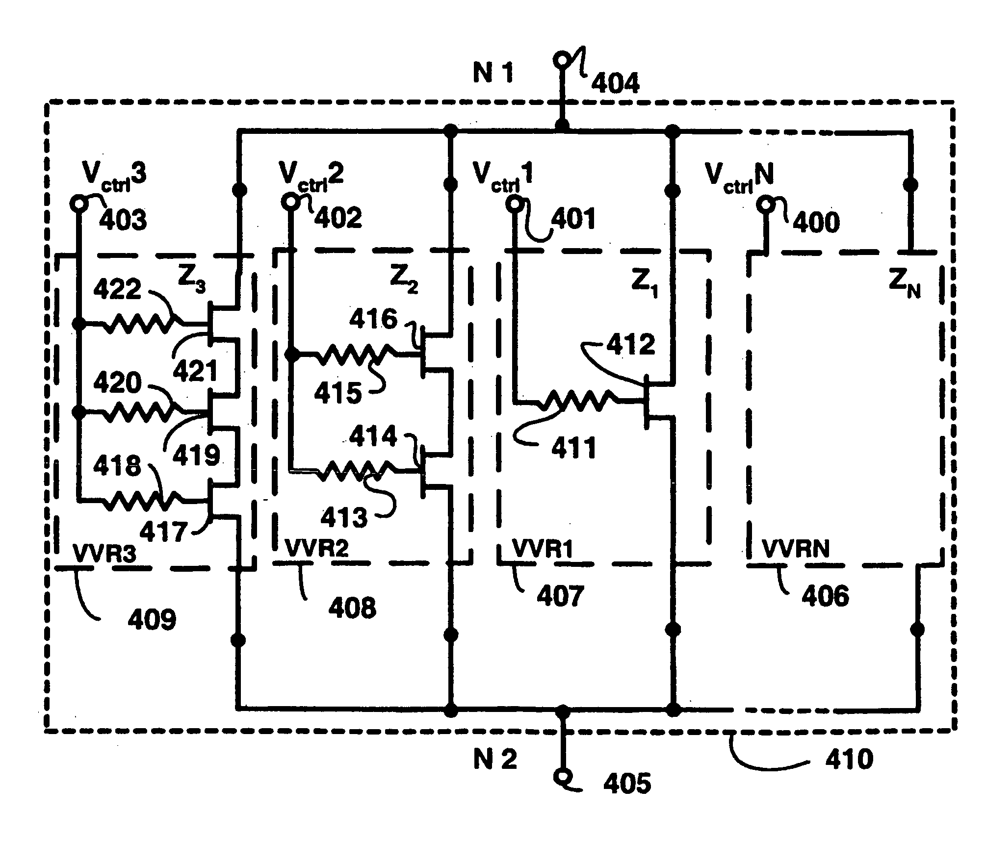
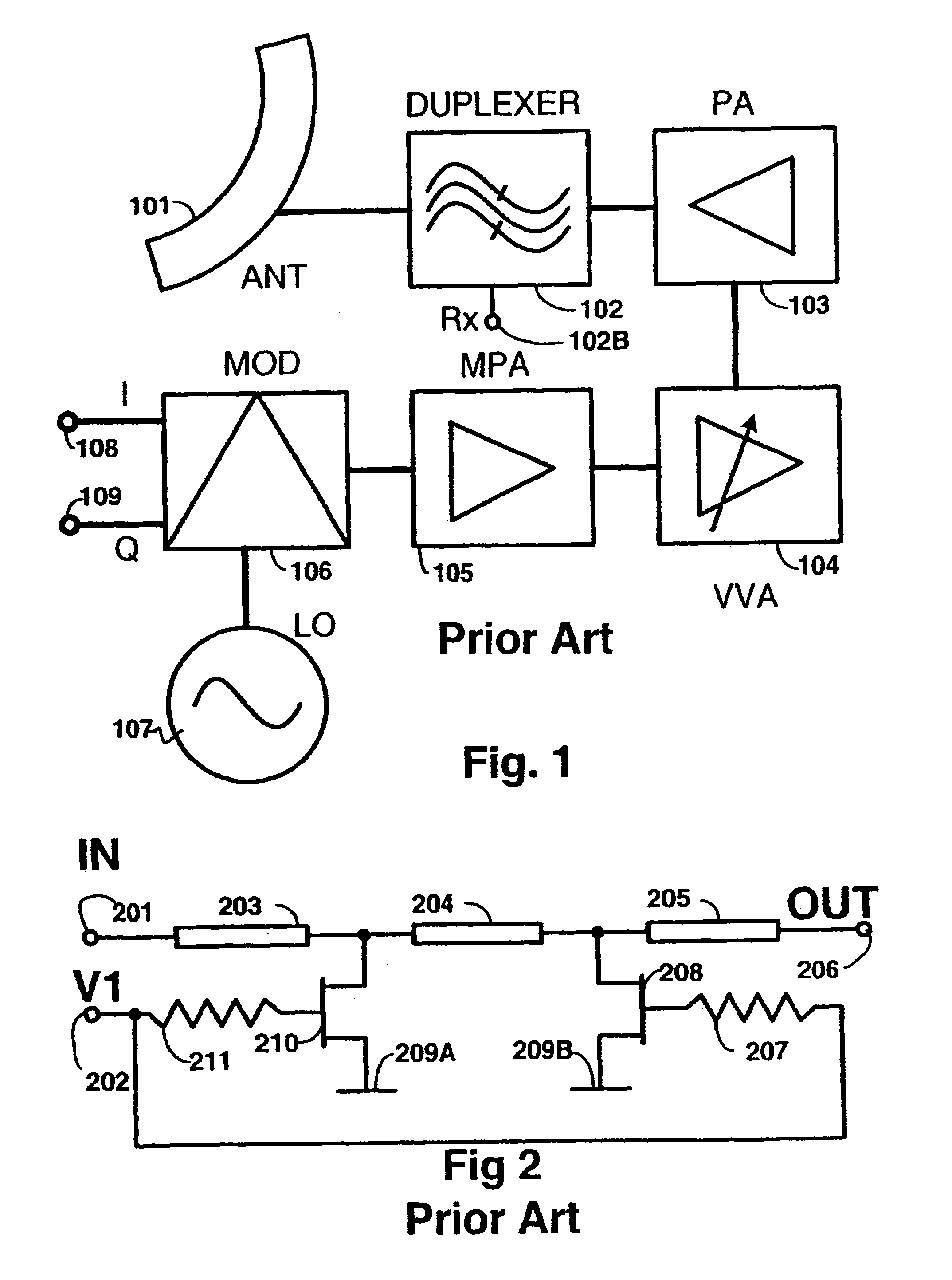
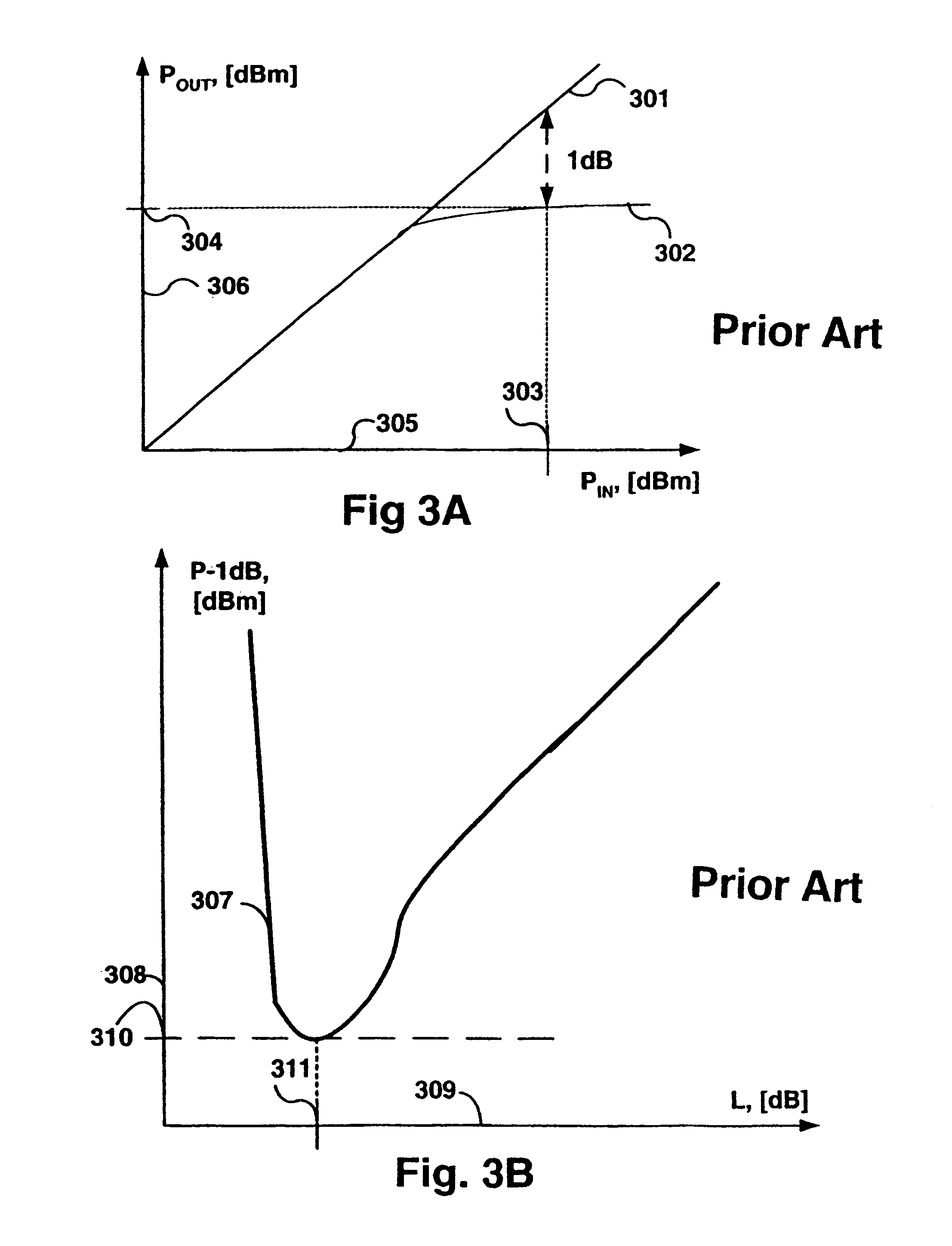
[0040]Above in the description of the prior art reference was made to FIGS. 1, 2, 3A and 3B, so the following description of the invention and its advantageous embodiments refers mainly to FIGS. 4A to 7.

[0041]FIG. 4A shows a VVR 410 according to an advantageous embodiment of the invention where each of the VVR blocks 406, 407, 408, 409 is connected in parallel with the other VVR blocks. Parallel connection is realized by connecting blocks 406, 407, 408, 409 to nodes 404 and 405 between them. The function of the nodes 404 and 405 depends e.g. on the connection of the VVR 410 in relation to the signal transmission line. This is illustrated by examples depicted by FIGS. 5A, 5B and 5C and the descriptions thereof. FIG. 4A shows VVR blocks VVR1407, VVR2408, VVR3409, and VVRN 406, all of which are independent VVRs having semiconductor-based inner structures of their own which will be described later on in conjunction with FIG. 4B.

[0042]Each of said VVR blocks has a control input of its ow...


PUM


Abstract

The invention discloses a new and original voltage variable resistor VVR with input and output ports and a first input and second input for control signals to set the impedance between the input and output ports as desired over a certain range and, thus, to optimize the operation of the VVR from the transmitter device control viewpoint as regards both the linearity and minimum impedance. The invention further discloses a method for controlling a VVR and a cellular radio system terminal.

Description

PRIORITY CLAIM[0001]This is a national stage of PCT application No. PCT / FI02 / 00662, filed on Aug. 12, 2002. Priority is claimed on that application and on application No. 20011634 filed in Finland on Aug. 13, 2001.BACKGROUND OF THE INVENTION[0002]The invention relates in general to electronics technology in wireless communications and in particular to the control of transmission power as specified in the preamble of the first claim.[0003]Optimization of transmission power is important in a portable terminal, for example, because if the transmission power is too low, it may cause annoying breaks in the connection or the connection may be lost altogether. If, on the other hand, the transmission power is too high, it may interfere with nearby devices and unnecessarily drain the power source of the portable device.[0004]Electronic components are known in which the resistance depends on the voltage between input and output. There are also components in which the resistance between the in...

Claims


Application Information

Patent Timeline
IPC IPC(8): H01P1/22H03H11/24
CPCH03H11/245
Inventor NYBERG, PETRI
Owner NOKIA TECHNOLOGLES OY
Learn More