Vehicle radar device

a radar device and vehicle technology, applied in the direction of distance measurement, instruments, surveying and navigation, etc., can solve the problems of reducing the detection range of the preceding vehicle, reducing the detection capability or accuracy of the vehicle, and reducing the detection capability or accuracy. , the effect of suppressing the decrease in angular resolution

Inactive Publication Date: 2007-01-02
DENSO CORP
View PDF14 Cites 18 Cited by
  • Summary
  • Abstract
  • Description
  • Claims
  • Application Information

AI Technical Summary

Benefits of technology

[0012]Therefore, in setting a predetermined number of received signals output based on the predetermined number of transmission signals radiated neighboring each other as a range of the received signals to be integrated, there are set a plurality of ranges of the received signals to be integrated while shifting the received signals belonging to the ranges of the received signals to be integrated by a number of the received signals smaller than the predetermined number, so that some o

Problems solved by technology

However, the output intensity of the transmission waves such as laser beams is limited due to a variety of reasons, and a limitation is inevitably imposed on the detectable range of distance to the preceding vehicles.
When the light signals are received in this case, it beco

Method used


Image

  • Vehicle radar device
  • Vehicle radar device
  • Vehicle radar device

Examples


Embodiment Construction

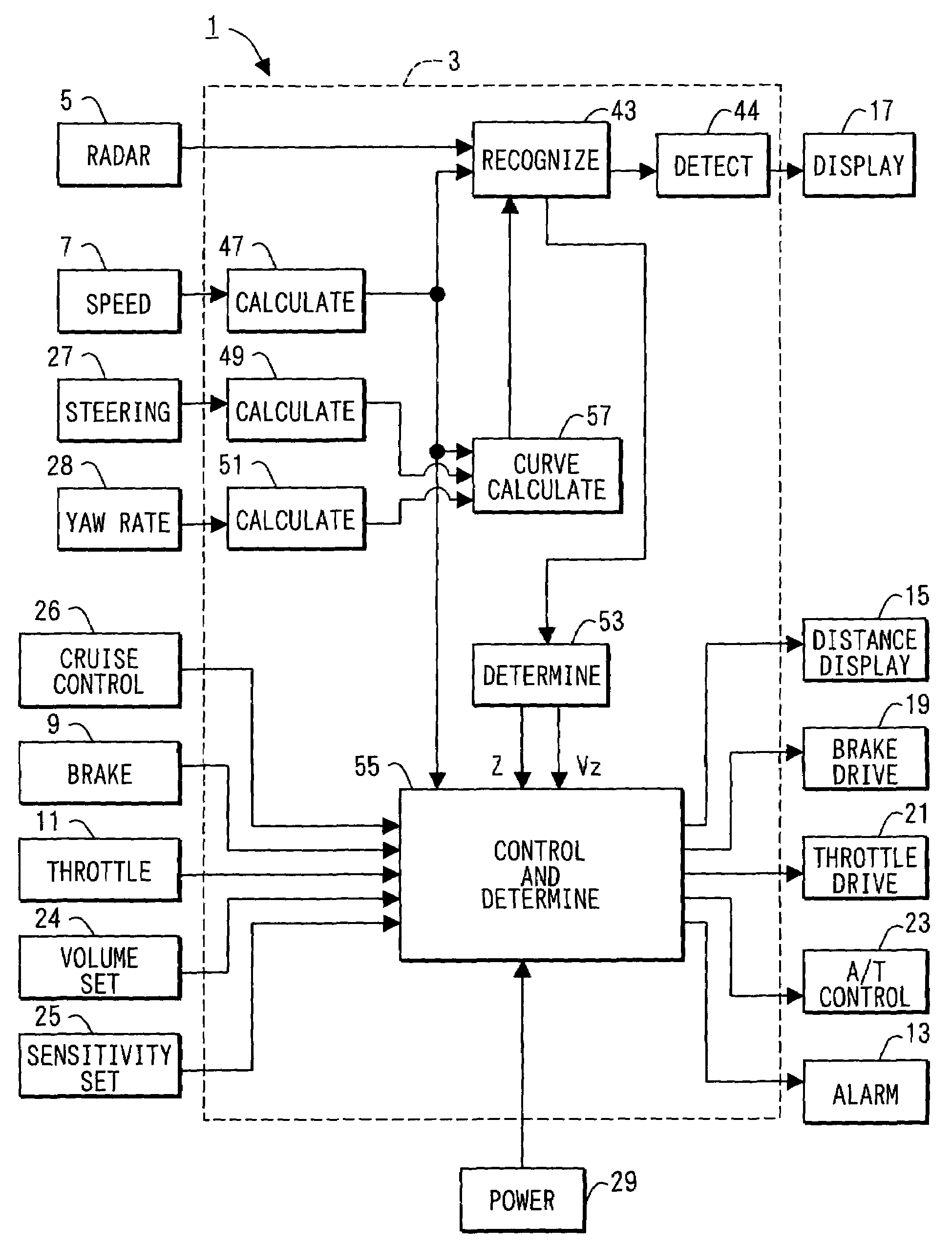
[0025]According to an embodiment of the present invention shown in FIG. 1, a vehicle radar device is applied to a vehicle control device 1 which operates to produce an alarm when there is an object in a region to be alerted based on a result detected by the vehicle radar device, and operates to control the vehicle to maintain a predetermined distance relative to the preceding vehicle.

[0026]The vehicle control device 1 is composed of a recognition / inter-vehicle distance control ECU 3 as a center. The recognition / inter-vehicle distance control ECU 3 is composed of a microcomputer, and includes an input / output interface (I / O), various drive circuits and detector circuits. Those hardware construction is known and hence not described here in detail.

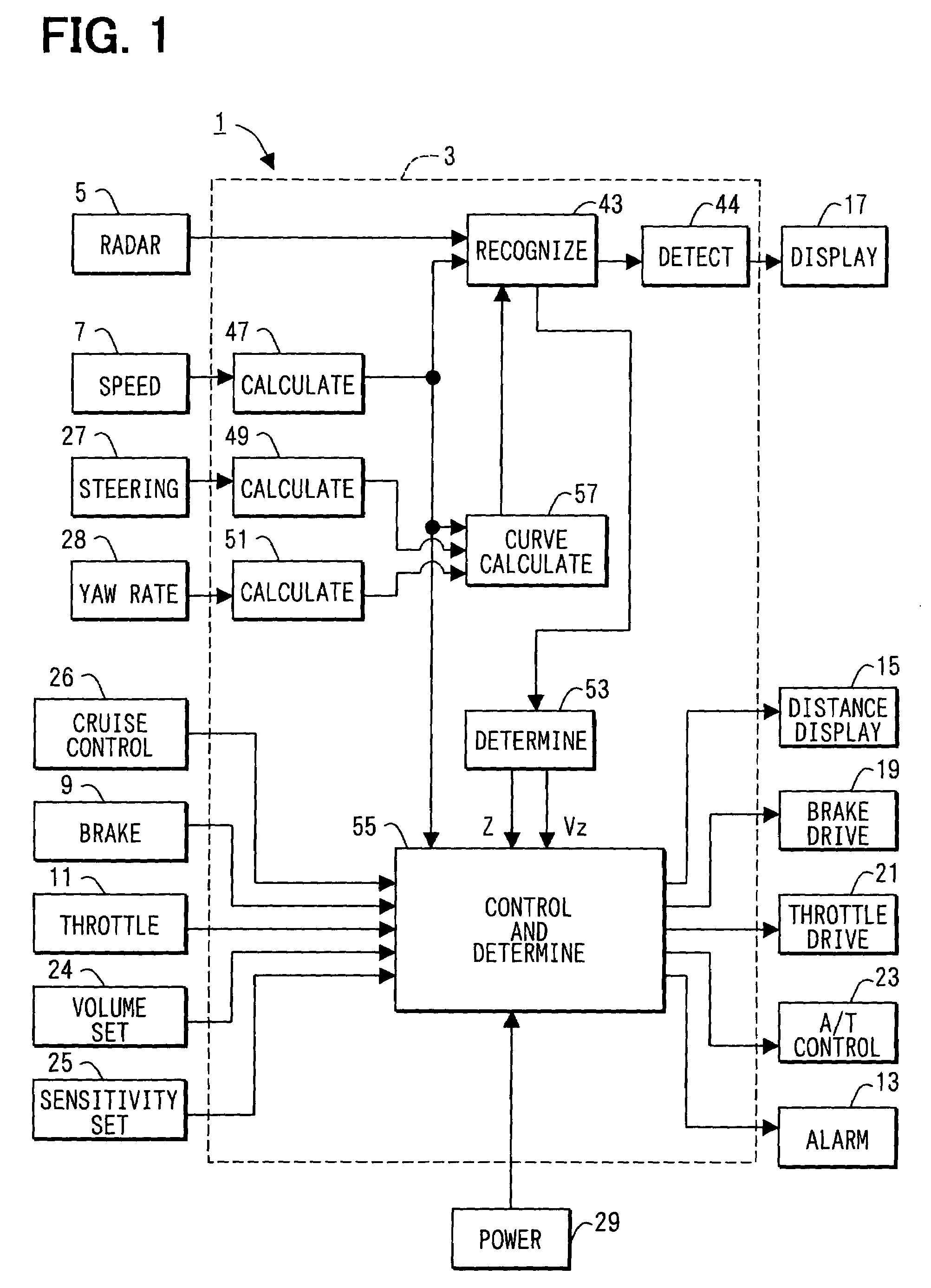
[0027]The recognition / inter-vehicle distance control ECU 3 receives detection signals from a laser radar sensor 5 which is a vehicle radar device, a vehicle speed sensor 7, a brake switch 9 and a throttle opening sensor 11, and sends drive sig...


PUM


Abstract

In a vehicle radar device, a predetermined number of received light signals output based on a predetermined number of laser beams radiated from a radar sensor are integrated by an integrator to produce an integrated signal. Integration of the predetermined number of received light signals helps amplify the received light signal components corresponding to the waves reflected by reflecting objects, making it possible to improve the sensitivity for detecting the waves reflected by the reflecting object. There are set a plurality of ranges of the received light signals to be integrated, each being shifted by one received light signal. This minimizes a drop in the angular resolution based on the integrated signals.

Description

CROSS REFERENCE TO RELATED APPLICATION[0001]This application is related to and incorporates herein by reference Japanese Patent Application No. 2002-346282 filed on Nov. 28, 2002.FIELD OF THE INVENTION[0002]This invention relates to a vehicle radar device, which radiates a plurality of transmission waves in the forward lateral direction, that is, within a range of a predetermined angle in at least a direction of the vehicle width, and detects objects based on received signals that vary depending upon the intensities of the reflected waves when the reflected waves are received in response to the transmitted signals.BACKGROUND OF THE INVENTION[0003]A conventional vehicle radar device radiates transmission waves such as light waves or millimeter waves toward the front of the vehicle and detects objects in front of the vehicle based on the reflected waves as disclosed in, for example, JP-A-2002-40139. The device of this kind is used for a device that generates an alarm upon detecting a ...

Claims


Application Information

Patent Timeline
IPC IPC(8): G01C3/08G01S17/931G08G1/16G01S7/292G01S7/486G01S7/493G01S17/42
CPCG01S7/486G01S17/936G01S17/42G01S7/4873G01S7/2926G01S17/931
Inventor HOASHI, YOSHIAKIMORIKAWA, KATSUHIRO
Owner DENSO CORP
Why Eureka
Try Eureka