Use of data latches in multi-phase programming of non-volatile memories

a technology of non-volatile memory and data latch, which is applied in the field of non-volatile semiconductor memory, can solve the problems of unsuitable mobile and handheld environment, bulky disk drives, and easy mechanical failure, and achieve the effect of avoiding mechanical failure, avoiding mechanical failure, and avoiding mechanical failur

Active Publication Date: 2007-01-02
SANDISK TECH LLC
View PDF79 Cites 153 Cited by
  • Summary
  • Abstract
  • Description
  • Claims
  • Application Information

AI Technical Summary

Problems solved by technology

Conventional mass storage, based on rotating magnetic medium such as hard drives and floppy disks, is unsuitable for the mobile and handheld environment.
This is because disk drives tend to be bulky, are prone to mechanical failure and have high latency and high power requirements.
These undesirable attributes make disk-based storage impractical in most mobile and portable applications.
It is often difficult to perform both of these functions in an optimum manner with a single voltage.
Programming of charge storage memory devices can only result in adding more charge to its charge storage elements.
However, as can be seen from FIG. 6A, the circuitry of a read / write module will likely be implemented with many more transistors and circuit elements and therefore will occupy a space over many columns.
However, the interleaving page architecture is disadvantageous in at least three respects.
First, it requires additional multiplexing circuitry.
Secondly, it is slow in performance.
Thirdly, it is also not optimum in addressing other disturb effects such as field coupling between neighboring charge storage elements at the floating gate level when the two neighbors are programmed at different times, such as separately in odd and even pages.
The problem of neighboring field coupling becomes more pronounced with ever closer spacing between memory transistors.
The conventional architecture of interleaving page exacerbates the error caused by neighboring floating gate coupling.
The read errors will become more severe with increasing density, requiring a more accurate read operation and coarser partitioning of the threshold window for multi-state implementation.
Performance will suffer and the potential capacity in a multi-state implementation is limited.

Method used


Image

  • Use of data latches in multi-phase programming of non-volatile memories
  • Use of data latches in multi-phase programming of non-volatile memories
  • Use of data latches in multi-phase programming of non-volatile memories

Examples


Embodiment Construction

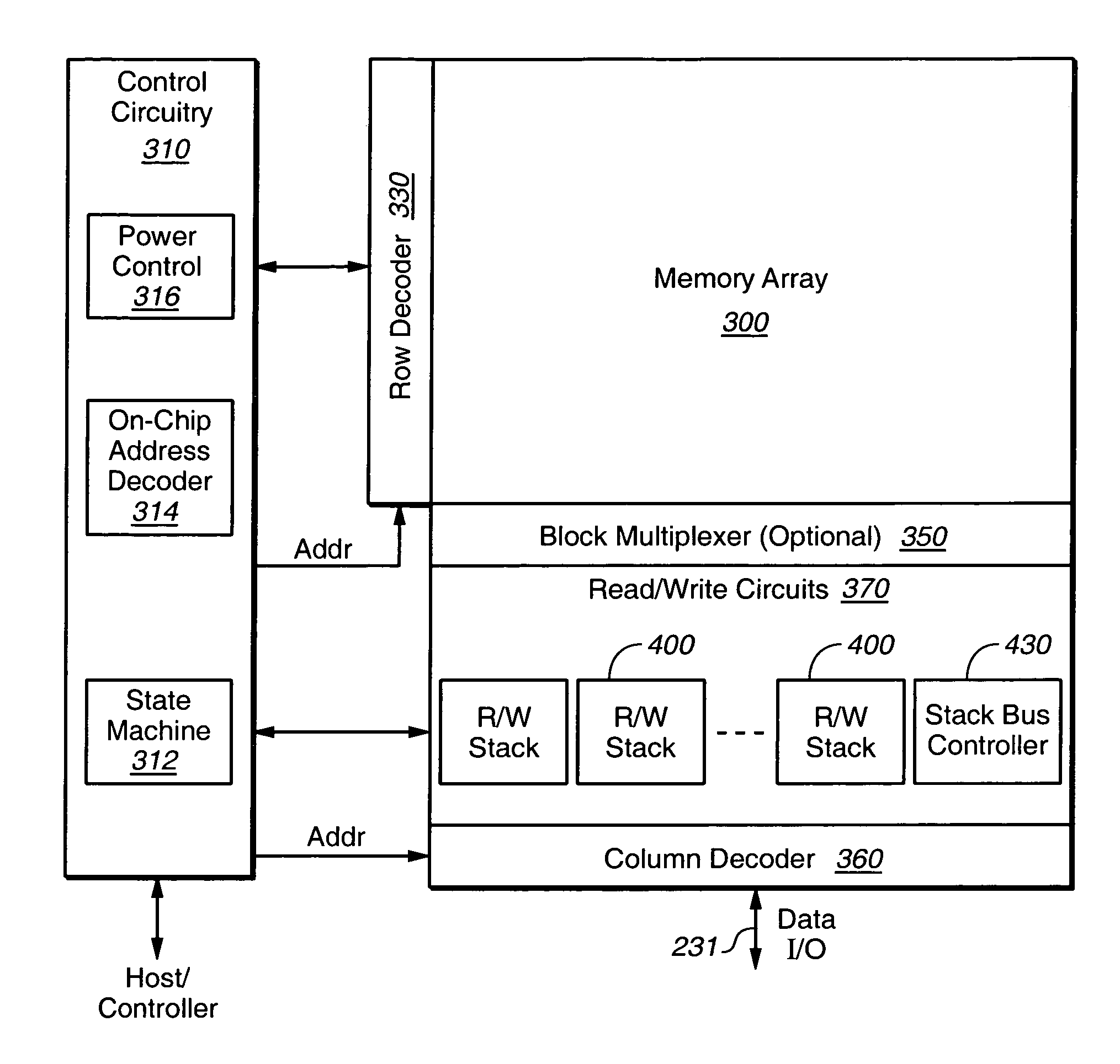
[0074]FIG. 7A illustrates schematically a compact memory device having a bank of partitioned read / write stacks, in which the improved processor of the present invention is implemented. The memory device includes a two-dimensional array of memory cells 300, control circuitry 310, and read / write circuits 370. The memory array 300 is addressable by word lines via a row decoder 330 and by bit lines via a column decoder 360. The read / write circuits 370 is implemented as a bank of partitioned read / write stacks 400 and allows a block (also referred to as a “page”) of memory cells to be read or programmed in parallel. In a preferred embodiment, a page is constituted from a contiguous row of memory cells. In another embodiment, where a row of memory cells are partitioned into multiple blocks or pages, a block multiplexer 350 is provided to multiplex the read / write circuits 370 to the individual blocks.

[0075]The control circuitry 310 cooperates with the read / write circuits 370 to perform memo...


PUM


Abstract

A non-volatile memory device includes circuitry for governing a multi-phase programming process in a non-volatile memory. The exemplary embodiment uses a quick pass write technique where a single programming pass is used, but the biasing of the selected memory cells is altered to slow programming as the memory cells approach their target values by raising the voltage level of the channels of the selected memory cells. A principle aspect of the present invention introduces a latch associated with the read / write circuitry connectable to each selected memory cell along a corresponding bit line for the storage of the result of the verify at this lower level.

Description

CROSS REFERENCE TO RELATED APPLICATIONS[0001]This application is related to the following U.S. patent applications: Ser. No. 11 / 013,125, filed Dec. 14, 2004; Ser. No. 11 / 026,536, filed Dec. 29, 2004; Ser. No. 11 / 015,199, filed Dec. 16, 2004; a patent application entitled “Non-Volatile Memory and Method with Power-Saving Read and Program-Verify Operations”, by Yan Li, Seungpil Lee, and Siu Lung Chan, filed Mar. 16, 2005; and a patent application entitled “Use of Data Latches in Cache Operations of Non-Volatile Memories”, by Yan Li and Emilio Yero, filed concurrently with the present application. These applications are incorporated herein by reference in their entirety for all purposes.FIELD OF THE INVENTION[0002]This invention relates generally to non-volatile semiconductor memory such as electrically erasable programmable read-only memory (EEPROM) and flash EEPROM, and specifically to methods of implementing quick pass write or other multi-phase programming techniques.BACKGROUND OF ...

Claims


Application Information

Patent Timeline
Patent Type & Authority Patents(United States)
IPC IPC(8): G11C7/10
CPCG11C16/3468G11C16/10G11C16/24G11C16/26
Inventor LI, YANCERNEA, RAUL-ADRIAN
Owner SANDISK TECH LLC
Why Eureka
Try Eureka