Seat belt arrangements for child safety seats

a seat belt and child safety technology, applied in the field of seat belt arrangements, can solve the problems of large difficulty in series production, easy damage to the housing, and limited load capacity

Active Publication Date: 2007-01-09
HOLMBERGS CHILDSAFETY HLDG
View PDF11 Cites 43 Cited by
  • Summary
  • Abstract
  • Description
  • Claims
  • Application Information

AI Technical Summary

Benefits of technology

[0010]When a tongue is entered into a cavity of the guiding member, the latch spring biases the latch to engage with the tongue. This latch spring can be positioned to only act against internal metal parts of the buckle mechanism. This makes it less sensitive to heat, since no polymeric parts are involved. If separate latching is desired, the latches are equipped with separate latch springs. These springs are preferably conical wire springs, which allow long travel with little obstruction.
[0011]The above-mentioned design of the buckle mechanism can be self-contained, which means that no housing is necessary for the buckle to remain operable. This is an important feature since the housing easily can be damaged in a potential collision.
[0013]The buckle mechanism of the present invention is furthermore designed to be modular, i.e. easily be equipped with alternative features such as ejector springs, ejector spring spacers, button with integrated return spring and / or external return spring, independent or simultaneous latching, one or several tongues, etc.

Problems solved by technology

This can be very dangerous in a potential collision.
This results in greater difficulty during series production in which all buckles must be manufactured to meet the force range limitations with statistical certainty.
The crash loads must then be transferred through the housing to the webbing, meaning that the magnitude of the loads it can carry is expressly limited through reliance on the polymeric housing to transfer load to the webbing.
This is an important feature since the housing easily can be damaged in a potential collision.

Method used


Image

  • Seat belt arrangements for child safety seats
  • Seat belt arrangements for child safety seats
  • Seat belt arrangements for child safety seats

Examples


Embodiment Construction

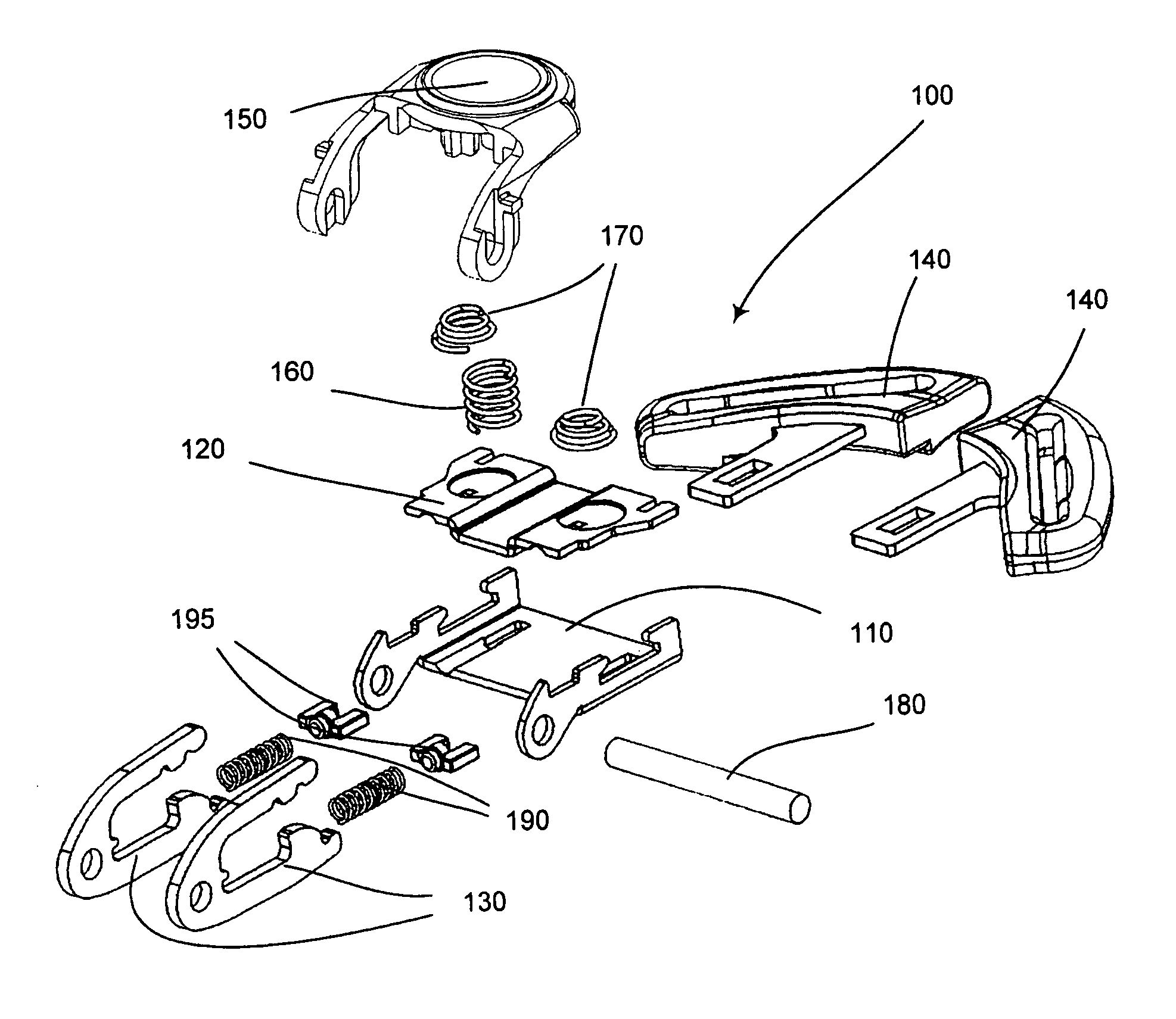
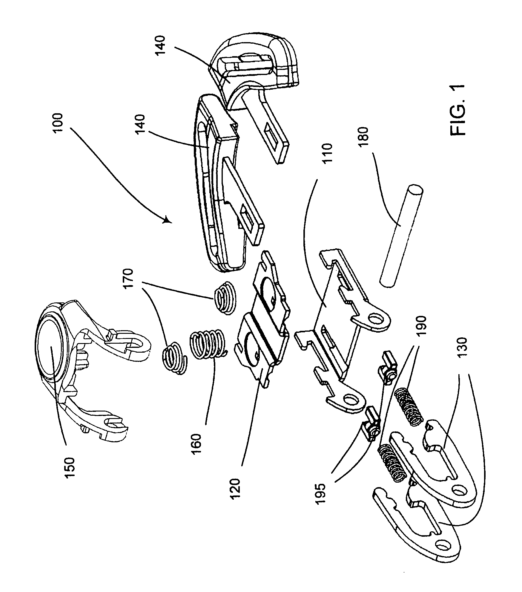
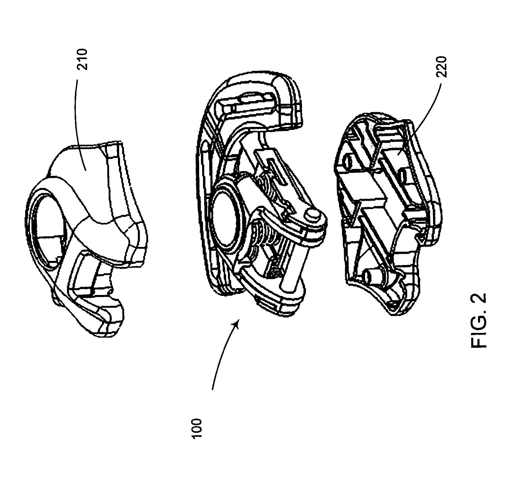
[0031]Reference is first made to FIG. 1, showing the different parts of a buckle mechanism 100 according to the present invention in an exploded view. The buckle mechanism 100 according to the present invention comprises lower 110 and upper plates 120, two latches 130, two tongue members 140, a button 150, a button return spring 160, two latch springs 170, an anchor pin 180 and optionally two ejector springs 190 and two ejector spring spacers 195. The buckle mechanism 100 is to be placed within a housing 200 consisting of an upper 210 and a lower casing 220, see FIGS. 2 and 14.

[0032]As is best shown in FIG. 3, the lower plate 110 is formed with a substantially flat central portion 111, having two sidewalls 112 projecting upwards at opposite sides of the flat portion 111. The flat portion 111 is further equipped with two openings 113 for receiving the two latches 130, and with two grooves 114, leading to the openings 113, for receiving the optional ejector springs 190 and ejector spr...


PUM


Abstract

A buckle mechanism for a seat belt arrangement of a child safety seat comprises a guiding member forming at least one internal cavity for guiding and receiving at least one tongue of a tongue member, at least one latch for engaging with and locking the at least one tongue and disengaging means for disengaging the at least one latch from the at least one tongue. The buckle mechanism further has the at least one latch pivotably secured and connected with an anchor pin, to which webbing of a seat belt is attached, the other webbing being attached in a way known per se to the at least one tongue member. The at least one latch engages with the at least one tongue and the force transmission from the webbings through the mechanism only consists of the at least one tongue, the at least one latch and the anchor pin.

Description

TECHNICAL FIELD[0001]The present invention relates to seat belt arrangements for automotive applications and, in particular, to child safety seats, where a buckle mechanism of the present invention is to be mounted. This buckle mechanism substantially comprises a guiding member, forming internal cavities for guiding and receiving tongues, latches for engaging with and locking the tongues and a button for disengaging the latches from the tongues.BACKGROUND OF THE INVENTION[0002]Seat belt arrangements for automotive applications are governed by laws and regulations regarding their design and construction. The seat belt arrangement must be safe to ensure proper protection of the passenger and the requirements to achieve this differ from country to country. Some countries require simultaneous latching of the tongues in the buckle to avoid that one tongue is improperly latched. In other countries it is required that the buckle is equipped with ejector means for ejecting the tongues out o...

Claims


Application Information

Patent Timeline
Patent Type & Authority Patents(United States)
IPC IPC(8): A44B11/26A44B11/00A44B11/25B60RB60R22/10
CPCA44B11/2549Y10S24/35Y10T24/45712Y10T24/45084Y10T24/45623
Inventor KARLSSON, ROJEL
Owner HOLMBERGS CHILDSAFETY HLDG
Why Eureka
Try Eureka