Cloverleaf microgyroscope with electrostatic alignment and tuning

a micro-gyroscope and electrostatic alignment technology, which is applied in the direction of instruments, turn-sensitive devices, calibration apparatuses, etc., can solve the problems of second harmonics, drift and scale factor stability performance degradation, and misalignment or coupling of drive motion into the output axis, so as to improve the accuracy of micro-gyroscope alignment and tuning, and improve the performance of closed loop micro-gyroscope performance

Inactive Publication Date: 2007-01-09
CALIFORNIA INST OF TECH +1
View PDF7 Cites 78 Cited by
  • Summary
  • Abstract
  • Description
  • Claims
  • Application Information

AI Technical Summary

Benefits of technology

[0016]It is an object of the present invention to improve closed loop micro-gyroscope performance. It is another object of the present invention to improve the accuracy of micro-gyroscope alignment and tuning.
[0017]It is a further object of the present invention to provide electrostatic alignment and tuning for closed-loop operation of a vibratory micro-gyroscope. It is still a further object of the present invention to use the quadr

Problems solved by technology
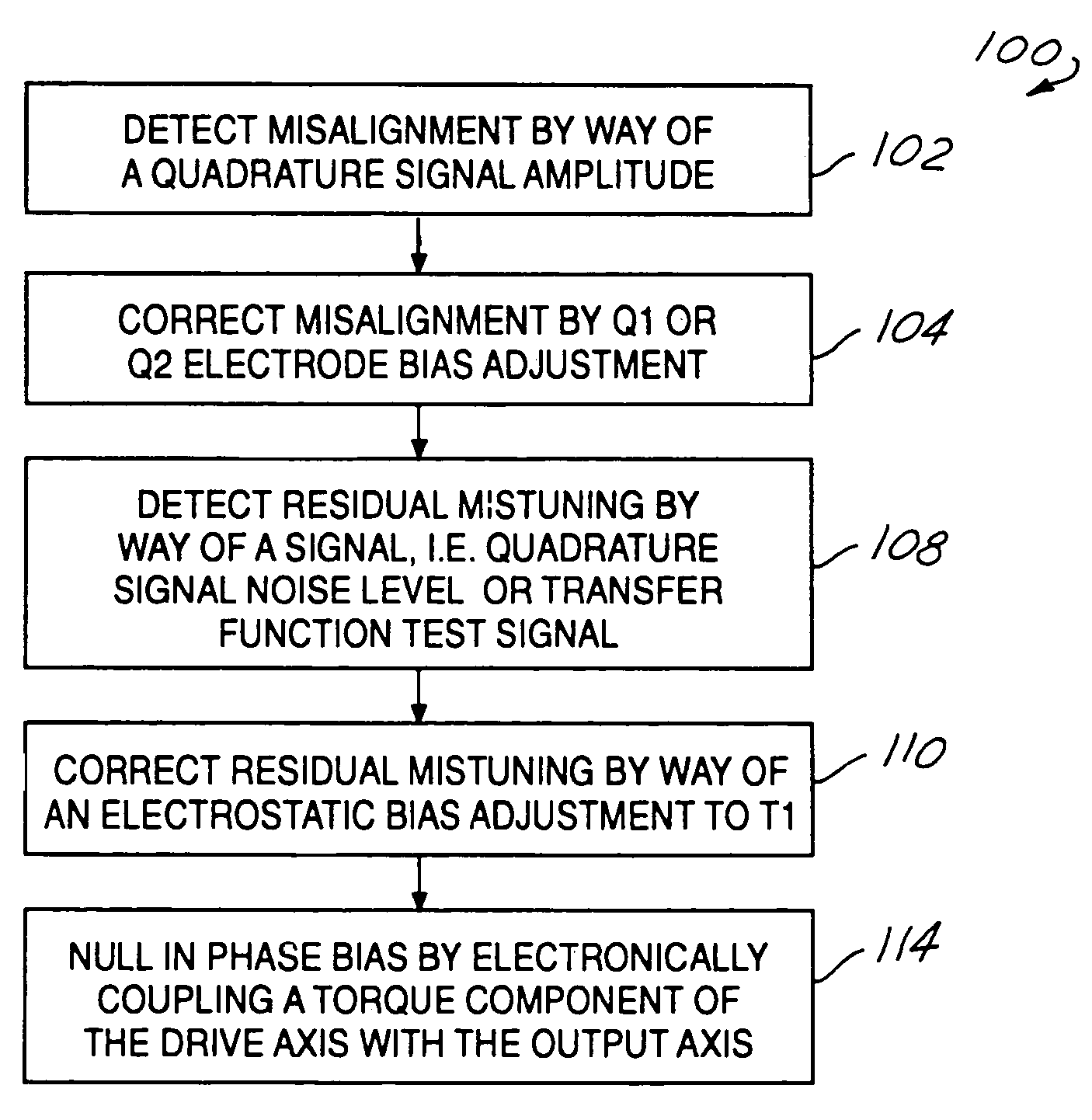
Micro-gyroscopes are subject to electrical interference that degrades performance with regard to drift and scale factor stability.
However, the use of a common frequency for both functions allows the relatively powerful drive signal to inadvertently electrically couple to the relatively weak sense signal.
Residual mechanical imbalance, either stiffness or mass imbalance, of a cloverleaf micro-gyroscope results in misalignment or coupling of drive motion into the output axis.
However, electronic alignment, in which the sense and control axes are aligned with the mechanical modal axes results in second harmonics and does

Method used


Image

  • Cloverleaf microgyroscope with electrostatic alignment and tuning
  • Cloverleaf microgyroscope with electrostatic alignment and tuning
  • Cloverleaf microgyroscope with electrostatic alignment and tuning

Examples


Embodiment Construction

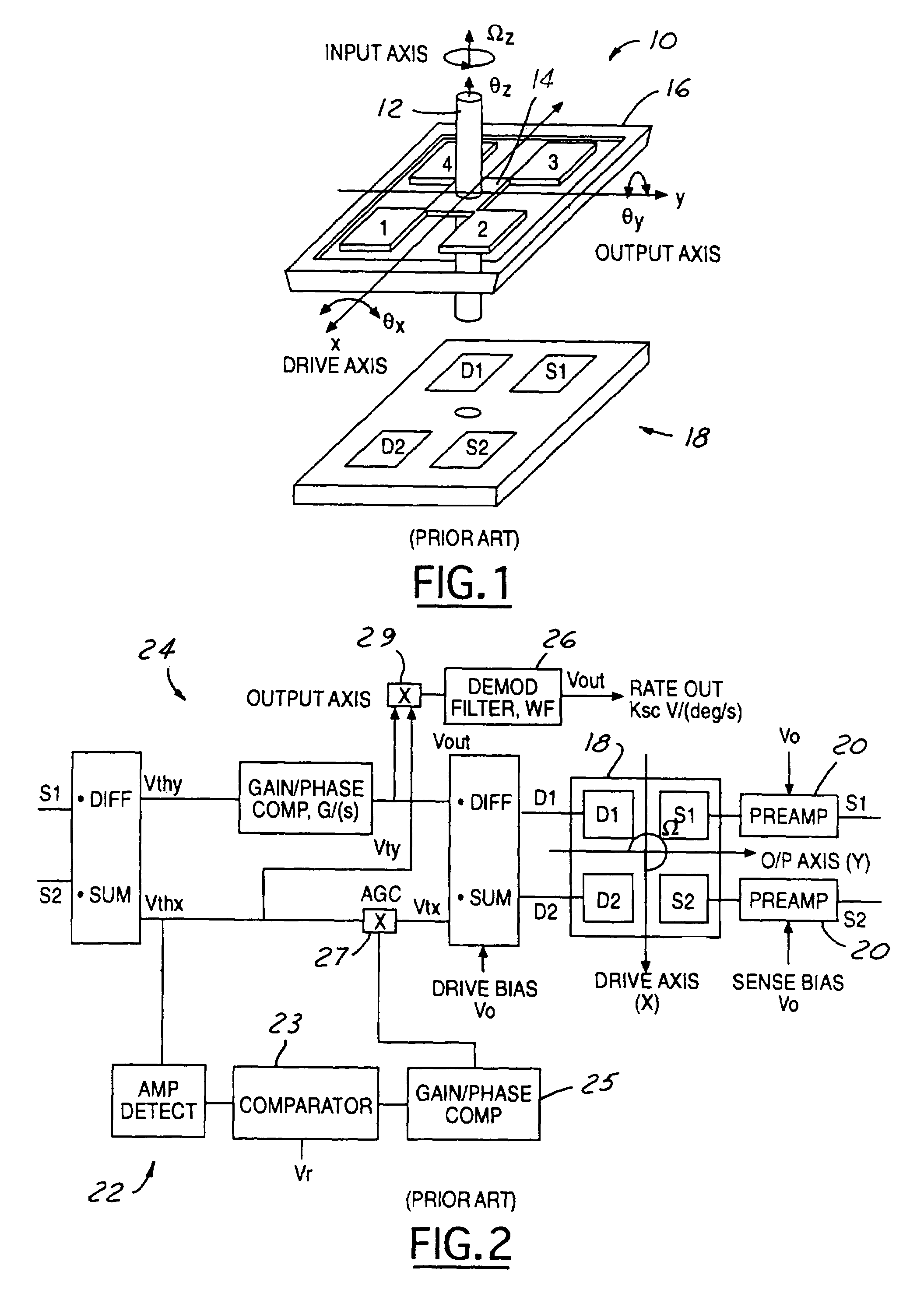
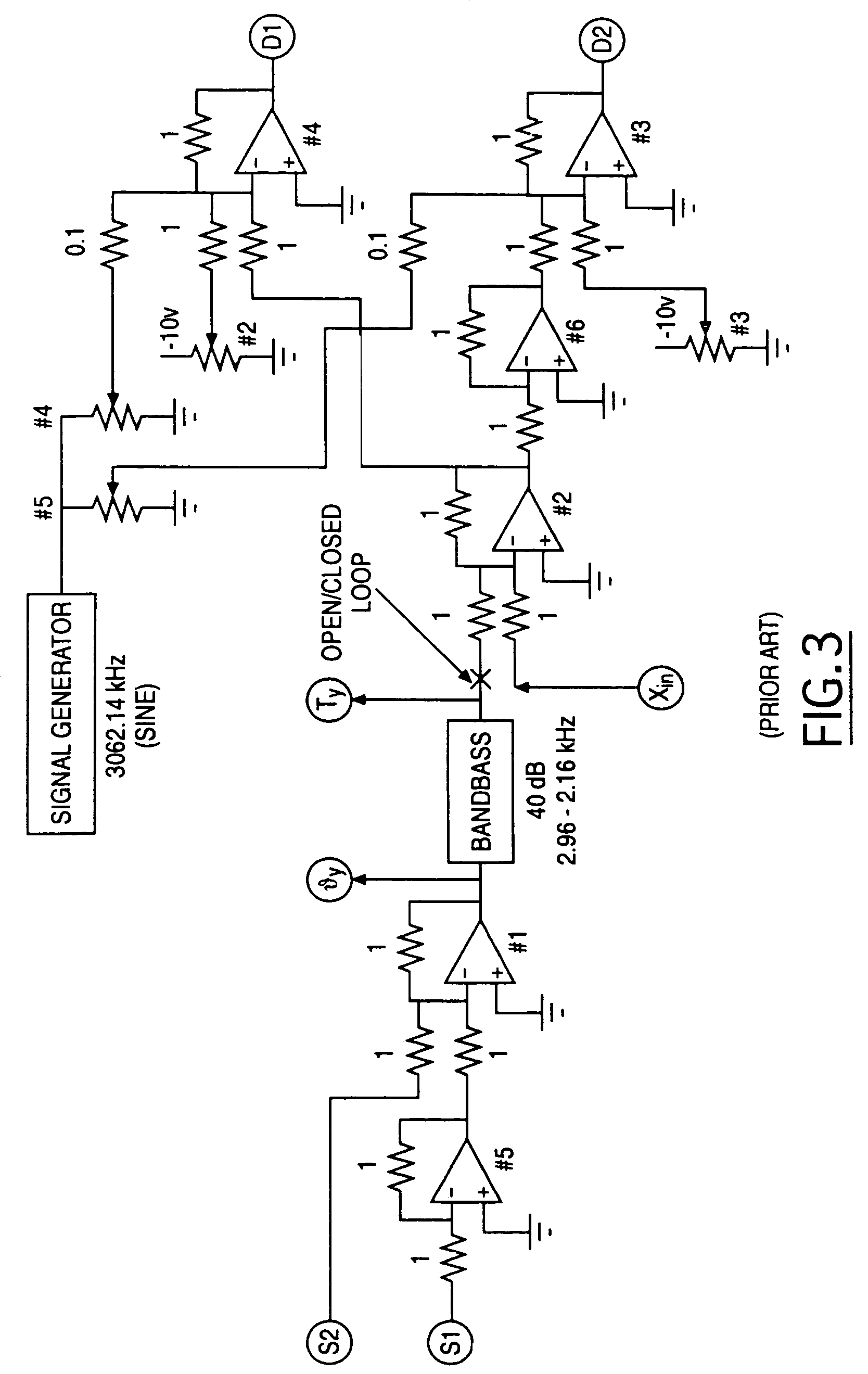
[0024]The method of the present invention is applicable to a closed loop micro-gyroscope. In the preferred embodiment, the closed loop micro-gyroscope is described in conjunction with FIGS. 1 through 3. For example purposes, and for simplicity, the closed loop control of the preferred embodiment will be described in accordance with a cloverleaf micro-gyroscope having four electrodes.

[0025]FIG. 1 is an exploded view of the micro-gyroscope 10. The cloverleaf micro-gyroscope 10 has an affixed central proof mass, or post 12 rigidly attached to a resonator 14 having a cloverleaf shape with petals labeled 1, 2, 3, and 4. The cloverleaf resonator 14 is elastically suspended from an outer frame 16. The resonator defines a resonator plane and the central proof mass 12 is perpendicular to the resonator plane.

[0026]A set of at least four electrodes 18 define an electrode plane. The electrodes 18 are located under the resonator 14. The electrodes function to actuate the resonator and to sense c...


PUM


Abstract

A micro-gyroscope (10) having closed loop output operation by a control voltage (Vty), that is demodulated by a drive axis (x-axis) signal Vthx of the sense electrodes (S1, S2), providing Coriolis torque rebalance to prevent displacement of the micro-gyroscope (10) on the output axis (y-axis) Vthy˜0. Closed loop drive axis torque, Vtx maintains a constant drive axis amplitude signal, Vthx. The present invention provides independent alignment and tuning of the micro-gyroscope by using separate electrodes and electrostatic bias voltages to adjust alignment and tuning. A quadrature amplitude signal, or cross-axis transfer function peak amplitude is used to detect misalignment that is corrected to zero by an electrostatic bias voltage adjustment. The cross-axis transfer function is either Vthy/Vty or Vtnx/Vtx. A quadrature signal noise level, or difference in natural frequencies estimated from measurements of the transfer functions is used to detect residual mistuning, that is corrected to zero by a second electrostatic bias voltage adjustment.

Description

CROSS REFERENCE[0001]The invention described herein is a Continuation-In-Part of application Ser. No. 09 / 927,858, filed Aug. 9, 2001, now abandoned.GOVERNMENT INTEREST[0002]The invention described herein was made in the performance of work under a NASA contract, and is subject to the provisions of Public Law 96-517 (35 U.S.C. § 202) in which the Contractor has elected to retain title.TECHNICAL FIELD[0003]The present invention relates to micro-machined electromechanical systems, and more particularly to a MEMS vibratory gyroscope having closed loop output.BACKGROUND ART[0004]Micro-gyroscopes are used in many applications including, but not limited to, communications, control and navigation systems for both space and land applications. These highly specialized applications need high performance and cost effective micro-gyroscopes.[0005]There is known in the art a micro-machined electromechanical vibratory gyroscope designed for micro-spacecraft applications. The gyroscope is explained...

Claims


Application Information

Patent Timeline
IPC IPC(8): G01C19/00G01C19/56G01C19/5719G01C25/00
CPCG01C19/56G01C25/00G01C19/5719G01P2015/084G01P2015/0842
Inventor CHALLONER, A. DORIANGUTIERREZ, ROMAN C.TANG, TONY K.
Owner CALIFORNIA INST OF TECH
Why Eureka
Try Eureka