Temperature controlled vacuum chuck

Inactive Publication Date: 2007-01-09
LITREX CORP
View PDF16 Cites 20 Cited by
  • Summary
  • Abstract
  • Description
  • Claims
  • Application Information

AI Technical Summary

Benefits of technology

[0016]One benefit of the vacuum chucks of the invention is the ability to secure a substrate in a desired placement while simultaneously heating the substrate in a uniform manner for controlling the cure rate of fluid materials deposited on the substrate and without overexposing the fluid materials to radiant

Problems solved by technology

This, however, can unnecessarily delay the manufacturing process, thereby increasing the associated manufacturing costs.
However, it can be difficult to position a heater directly above the fluid material during the deposition processes, which may be required to uniformly heat the fluid material.
Furthermore, even when a heater can be

Method used


Image

  • Temperature controlled vacuum chuck
  • Temperature controlled vacuum chuck
  • Temperature controlled vacuum chuck

Examples


Embodiment Construction

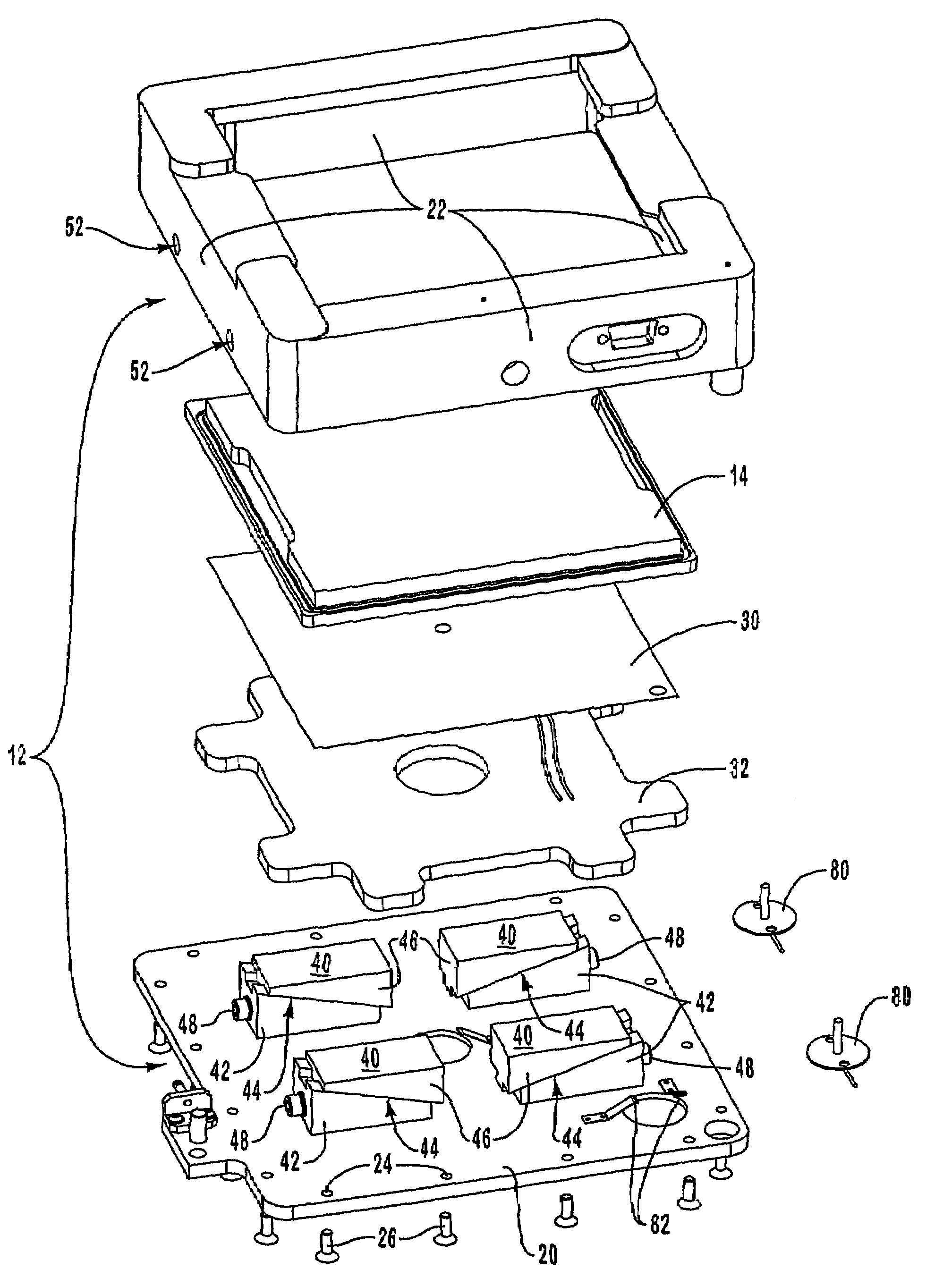
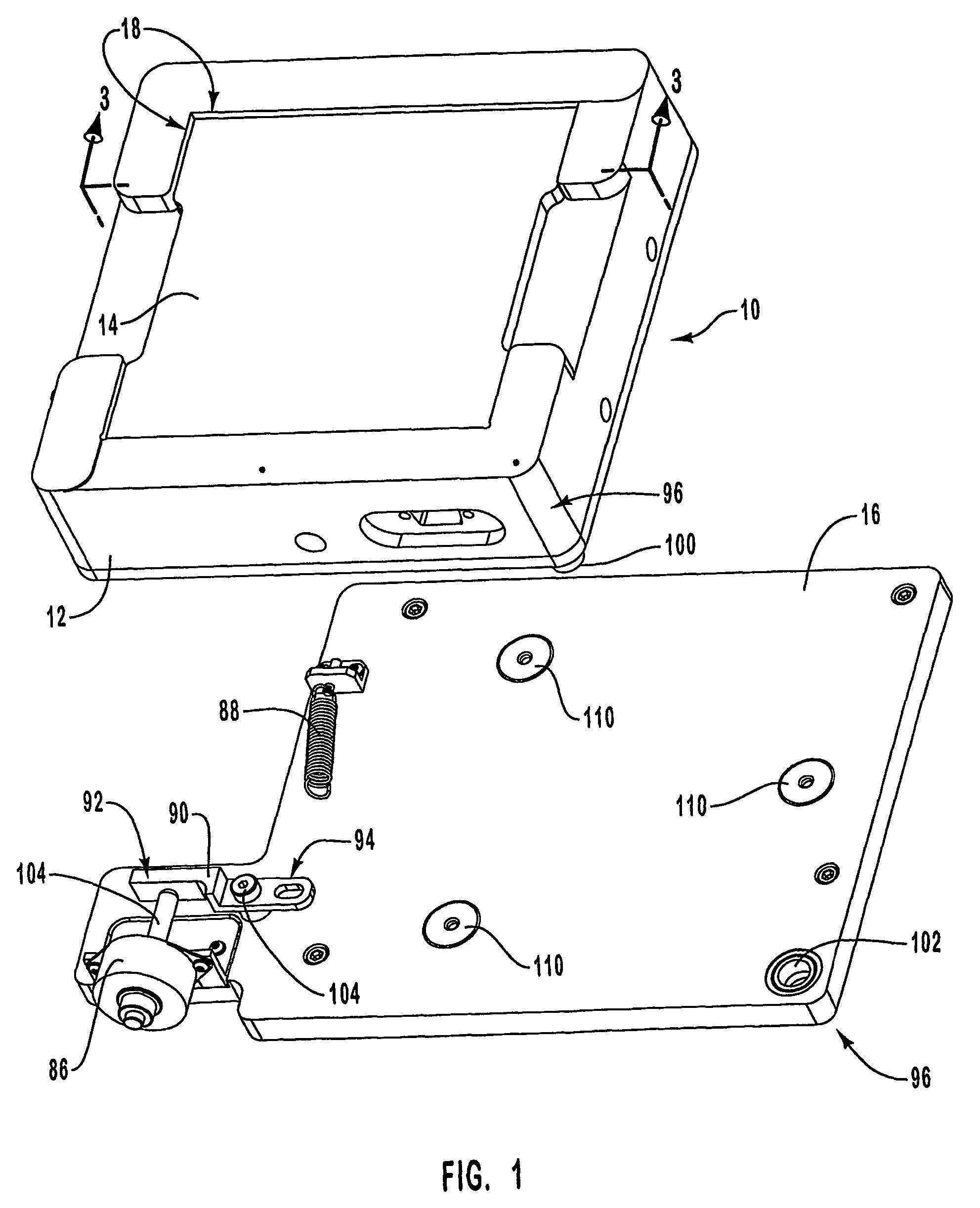
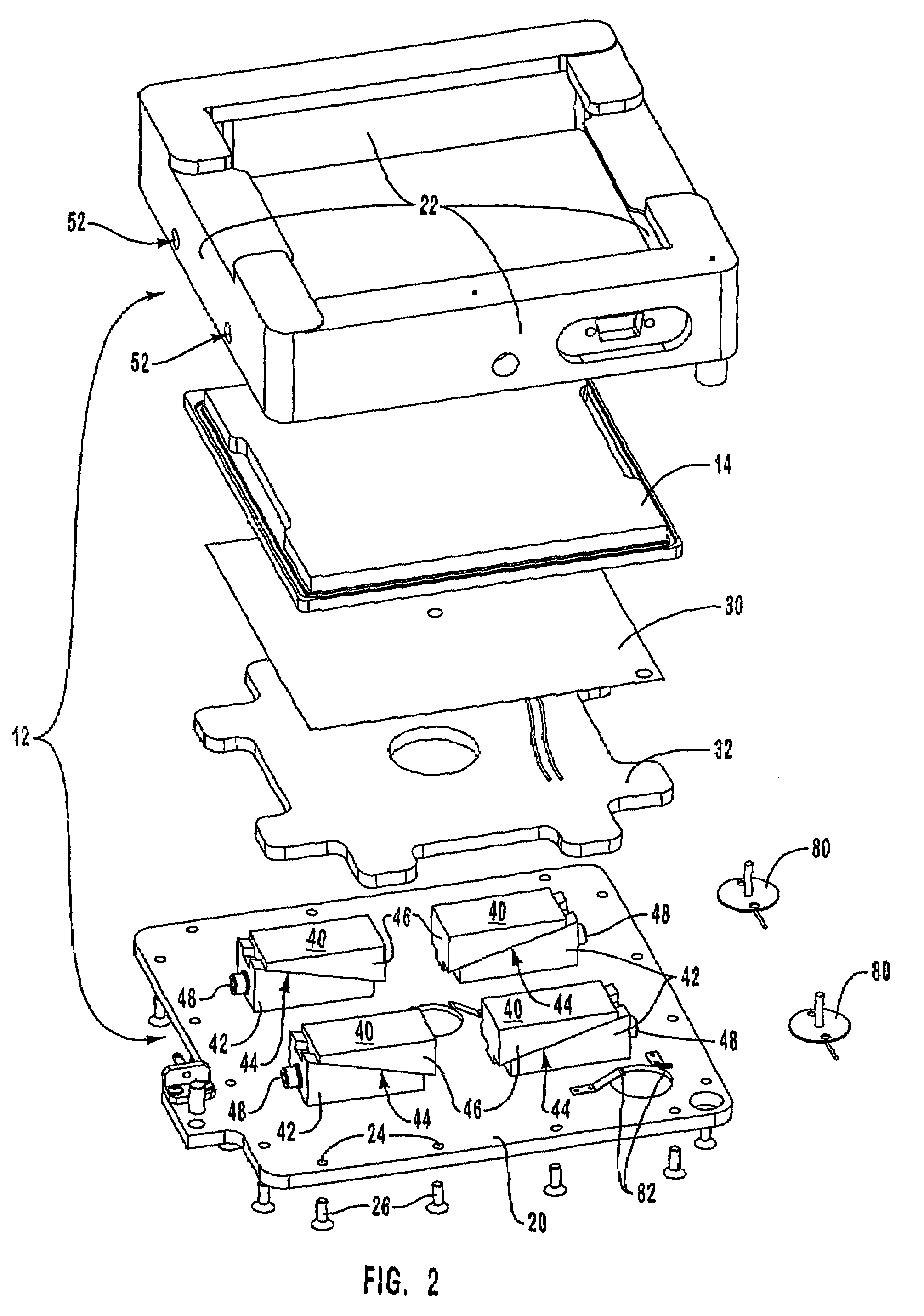
[0032]The present invention is generally directed to temperature controllable vacuum chucks and, more specifically, to vacuum chucks configured to secure a substrate in a desired placement while simultaneously heating the substrate in a manner that is sufficient for providing control over the cure rate of fluid materials deposited on the substrate.

[0033]The terms “fluid manufacturing material” and “fluid material,” as defined herein, should be broadly construed to include any material that can assume a low viscosity form and which is suitable for being deposited onto a substrate for forming a microstructure. Fluid materials may include, but are not limited to, light-emitting polymers (LEPs), which can be used to form polymer light-emitting diode display devices (PLEDs, and PolyLEDs). Fluid materials may also include plastics, metals, waxes, solders, solder pastes, biomedical products, acids, photoresists, solvents, adhesives, epoxies, and the like.

[0034]The term “deposit” is general...


PUM

PropertyMeasurementUnit
Temperatureaaaaaaaaaa
Pressureaaaaaaaaaa

Abstract

A temperature controllable vacuum chuck includes a mounting bracket, a porous plate, a heating element, and a temperature sensor. The porous plate is mounted to the mounting bracket and is configured for securing a substrate to the vacuum chuck when air is suctioned out of the vacuum chuck. The heating element is attached to the bottom of the porous plate and uniformly heats the porous plate, thereby heating any substrate mounted on the vacuum chuck and enabling control over the cure rate of fluid materials deposited on the substrate. The temperature sensor measures the temperature of the porous plate so that it can be adjusted when desired with a user controllable temperature control component.

Description

CROSS-REFERENCE TO RELATED APPLICATIONS[0001]This application claims the benefit of U.S. Provisional Patent Application Ser. No. 60 / 295,118, entitled “Formation of Microstructures Using Piezo Deposition of Liquid Onto Substrate,” filed Jun. 1, 2001, and U.S. Provisional Application Ser. No. 60 / 295,100, entitled Formation Of Printed Circuit Board Structures Using Piezo Deposition Of Liquid Onto Substrate, filed Jun. 1, 2001, each of which is incorporated herein by reference.DISCUSSION OF THE INVENTION[0002]The present invention relates to the field of vacuum chucks and, more specifically, to the field of vacuum chucks configured to secure substrates during printing or deposition procedures.[0003]Manufacturers have developed various techniques for creating microstructures on substrates such as, for example, light-emitting diode (LED) display devices, liquid crystal display (LCD) devices, printed circuit boards (PCBs) and the like. The quality of such devices is dependent on several fa...

Claims


Application Information

Patent Timeline
IPC IPC(8): B23B5/22B25B11/00B29C67/00B41J2/045B41J3/54H01L21/00H01L21/683H05K1/02H05K3/12
CPCB25B11/005B41J2/04505B41J2/0451B41J2/04558B41J2/0456B41J2/04573B41J2/04575B41J2/04581B41J2/04591B41J3/543H01L21/67103H01L21/6715H01L21/67248H01L21/6838H05K3/125B29C67/0059Y10T279/11B41J2202/04H05K1/0269B29C64/112
Inventor EDWARDS, CHARLES O.ALBERTALLI, DAVIDGRATCHEV, OLEG
Owner LITREX CORP
Why Eureka
Try Eureka