Plural layer anisotropic conductive connector and its production method

a technology of anisotropic conductive connectors and production methods, which is applied in the direction of connection contact materials, coupling device connections, instruments, etc., can solve the problems of reducing the conductivity of the conductive path-forming parts, affecting the electrical connection of the circuit device, and the pitch of the metallic electrode structure in the sheet-like connectors is small, so as to achieve stable conductivity and achieve advantageously and surely produced

Inactive Publication Date: 2007-01-09
ISC CO LTD
View PDF14 Cites 19 Cited by
  • Summary
  • Abstract
  • Description
  • Claims
  • Application Information

AI Technical Summary

Benefits of technology

[0017]The present invention has been made on the basis of the foregoing circumstances and has as its first object the provision of an anisotropically conductive connector which is prevented from causing permanent deformation by the contact of the target electrodes to be connected with pressure and deformation by abrasion even if the target electrodes to be connected are those projected, and achieves stable conductivity over a long period of time even when it is pressed repeatedly.
[0018]A second object of the present invention is to provide an anisotropically conductive connector which is suitable for use in electrical inspection of circuit devices, prevented from causing permanent deformation by the contact of electrodes to be inspected in a circuit device with pressure and deformation by abrasion even if the electrodes to be inspected of the circuit device are those projected, and achieves stable conductivity over a long period of time even when it is pressed repeatedly.
[0019]A third object of the present invention is to provide an anisotropically conductive connector with which a migration of an electrode material of electrodes to be inspected to conductive particles is prevented or inhibited, achieves stable conductivity over a long period of time and can be prevented or inhibited from adhering to a circuit device even when it is used in a state brought into contact under pressure with the circuit device under a high-temperature environment, in addition to the second object.

Problems solved by technology

However, the following problems are involved when a conventional anisotropically conductive sheet is used as a connector in electrical inspection of a circuit device having projected electrodes composed of, for example, a solder.
As a result, a problem that the conductivity of the conductive path-forming parts is lowered arises.
In the jig for inspection of circuit devices, however, it is difficult to achieve necessary electrical connection to a circuit device, which is an inspection target, when the arrangement pitch of electrodes to be inspected of the circuit device is small, i.e., the pitch of the metallic electrode structures in the sheet-like connector is small.
Therefore, the metallic electrode structures in the sheet-like connector cannot be brought into contact with certainly with all electrodes to be inspected in a circuit device, which is an inspection target, when the circuit device is such that a surface accuracy of its substrate is low, an evenness of the thickness of the substrate is low, or variations of the height of the electrodes to be inspected is great.
As a result, good electrical connection to such a circuit device cannot be achieved.
Even if it is possible to achieve a good electrically connected state to all the electrodes to be inspected, considerably great pressurizing force is required.
Accordingly, the whole inspection apparatus becomes a large in scale, and the production cost of the whole inspection apparatus becomes high.
As a result, it is difficult to stably retain the good electrically connected state.
Therefore, the production cost of the jig for inspection becomes high.
Further, the conventional anisotropically conductive sheets involve the following problem.
Thereby the work of changing the circuit device after completion of the inspection to an uninspected circuit device cannot be smoothly conducted.
As a result, inspection efficiency of circuit devices is lowered.
When the anisotropically conductive sheet adheres to the circuit device in great strength in particular, it is difficult to separate the anisotropically conductive sheet from the circuit device without damaging it.
Therefore, such an anisotropically conductive sheet cannot be used in the following inspection.

Method used


Image

  • Plural layer anisotropic conductive connector and its production method
  • Plural layer anisotropic conductive connector and its production method
  • Plural layer anisotropic conductive connector and its production method

Examples


example 1

[0252](a) Preparation of supporting body and mold:

[0253]A supporting body of a structure shown in FIG. 4 and a mold for molding an anisotropically conductive film of a structure shown in FIG. 6 were prepared in accordance with the following conditions.

[Supporting Body]

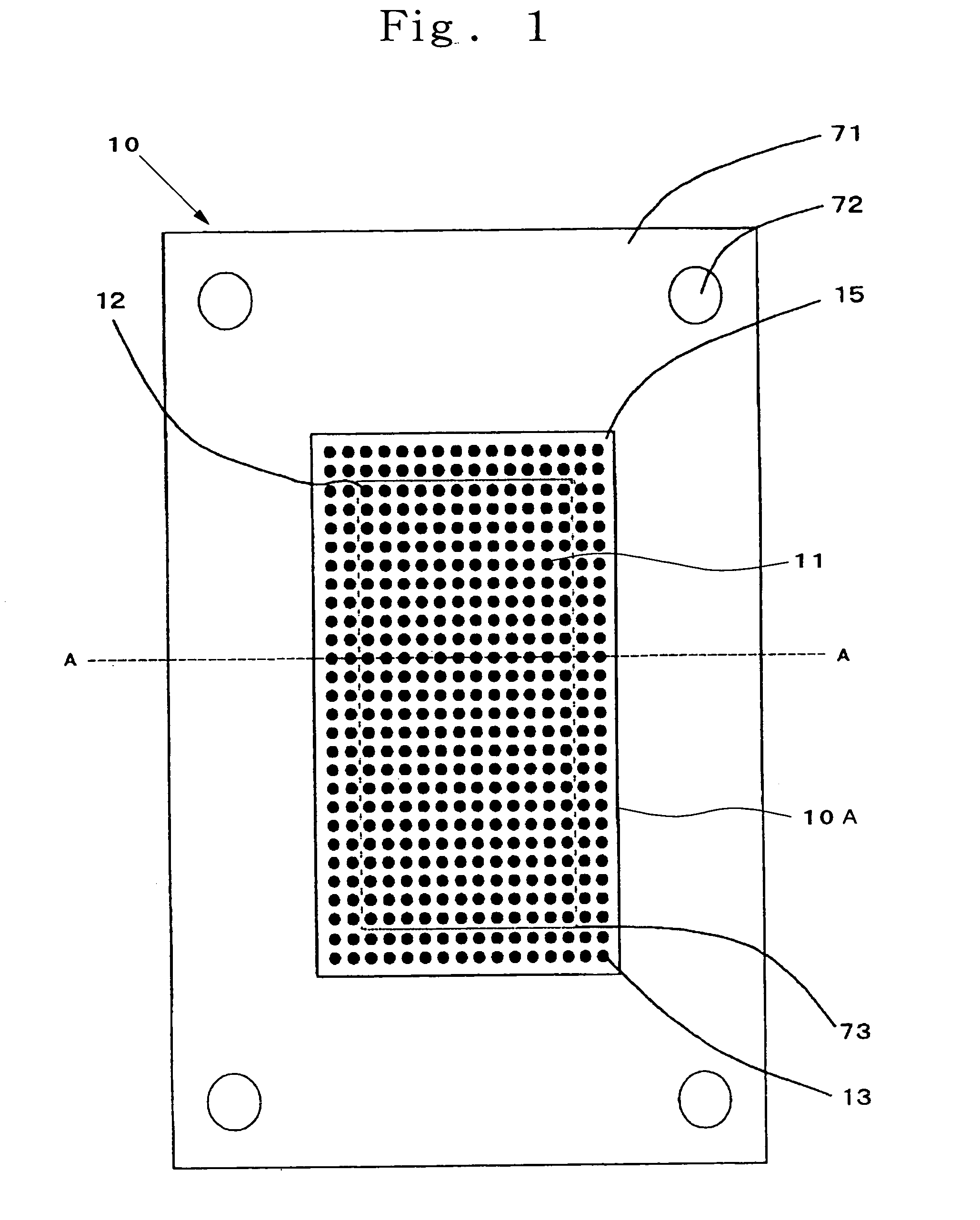
[0254]The supporting body (71) is such that its material is SUS304, the thickness is 0.1 mm, the size of an opening (73) is 17 mm×10 mm, and positioning holes (72) are provided at 4 corners.

[Mold]

[0255]Ferromagnetic substance substrates (51, 56) are such that their materials are iron, and the thickness is 6 mm.

[0256]Ferromagnetic substance layers (52, 57) are such that their materials are nickel, the diameter is 0.45 mm (circular), the thickness is 0.1 mm, the arrangement pitch (center distance) is 0.8 mm, and the number of the ferromagnetic substance layers is 288 (12×24).

[0257]Non-magnetic substance layers (53, 58) are such that their materials are dry film resists subjected to a curing treatment, the thickness of po...

example 2

[0269]An anisotropically conductive connector was produced in the same manner as in Example 1 except that addition type liquid silicone rubber (4) was used in place of the addition type liquid silicone rubber (5) in the preparation of the first molding material.

[0270]This anisotropically conductive connector will hereinafter be referred to as “Anisotropically Conductive Connector B2”.

example 3

[0271]An anisotropically conductive connector was produced in the same manner as in Example 1 except that addition type liquid silicone rubber (1) was used in place of the addition type liquid silicone rubber (2) in the preparation of the second molding material.

[0272]This anisotropically conductive connector will hereinafter be referred to as “Anisotropically Conductive Connector B3”.


PUM


Abstract

An anisotropically conductive connector, not causing permanent deformation by contact of target electrodes to be connected with pressure and deformation by abrasion even if the target electrodes are projected, and achieving stable conductivity over a long time period even when pressed repeatedly, a production process thereof, and an inspection circuit board equipped with the connector. The connector includes (1) anisotropically conductive film, with plural conductive path-forming parts each extending in a thickness-wise direction of the film arranged insulated by insulating parts and including at least 2 elastic layers, which are each formed by an insulating elastic polymeric substance, and (2) conductive particles exhibiting magnetism in portions of the respective elastic layers, at which conductive path-forming parts are formed. The connector satisfies H1≧30, and H1 / H2≧1.1, H1, H2 being durometer hardnesses of the elastic polymeric substance of one of elastic layers forming surfaces of the film, and of the elastic polymeric substance of the other, respectively, the resulting connector includes one harder elastic layer to limit permanent deformation and one softer layer for compliance.

Description

TECHNICAL FIELD[0001]The present invention relates to an anisotropically conductive connector suitable for use in, for example, inspection of circuit devices such as semiconductor integrated circuits and a production process thereof, and an inspection apparatus for circuit devices, which is equipped with this anisotropically conductive connector, and particularly to an anisotropically conductive connector suitable for use in inspection of circuit devices such as semiconductor integrated circuits having projected electrodes and a production process thereof, and an inspection apparatus for circuit devices.BACKGROUND ART[0002]An anisotropically conductive sheet is a sheet exhibiting conductivity only in its thickness-wise direction or having pressure-sensitive conductive conductor parts exhibiting conductivity only in the thickness-wise direction when they are pressed in the thickness-wise direction. Since the anisotropically conductive sheet has such features that compact electrical c...

Claims


Application Information

Patent Timeline
Patent Type & Authority Patents(United States)
IPC IPC(8): H01R12/00G01R1/04G01R1/073H01R4/04H01R13/24H01R43/00
CPCG01R1/0416G01R1/07314H01R4/04H01R43/007H01R13/2414Y10S439/923H01R2201/20H01R43/00H01R33/76H01R11/01
Inventor YAMADA, DAISUKEMAYUMI, KAZUAKIKIMURA, KIYOSHI
Owner ISC CO LTD
Why Eureka
Try Eureka