Photovoltaic power generation systems and methods of controlling photovoltaic power generation systems

a power generation system and photovoltaic technology, applied in the field of photovoltaic power generation systems, can solve the problems of high cost of solar cell modules, unsatisfactory application of solar cells high in power generation cost to power plants, and potential electric shock hazards, and achieve the effect of low cost and high safety

Inactive Publication Date: 2007-01-09
CANON KK
View PDF23 Cites 149 Cited by
  • Summary
  • Abstract
  • Description
  • Claims
  • Application Information

AI Technical Summary

Benefits of technology

[0017]The present invention has been accomplished in order to solve the above-stated problems and it is an object of the present invention to provide photovoltaic power generation systems with high safety and of low cost that can prevent an electric shock haz

Problems solved by technology

The solar cell modules are thus commercially available and are beginning to spread, but the solar cell modules involve an issue of still high cost, because a lot of coatings and insulators need to be used for ensuring the safety.
Consequently, they are still unsatisfactory for application of solar cells high in power generation cost to power plants and thus are not used widely.
On the other hand, there is a danger that an electric shock hazard may occur when a person except for a manager intrudes into a hazard controlled area in the power plants and the like, and it can extend to an accident in the electric power system.
In the conventional power plants such as thermal power plants, atomic power plants, and so on, however, if the system is brought once to a halt, a considerable time will be required for a restart of the system and thus the halt will cause great disadvantage.
In the photovoltaic power generation system and the method of protecting the photovoltaic power generation system, the solar cell string is judged abnormal when the voltage value between the detection terminals thereof becomes not more than the predetermined value, the power output terminals of this solar cell string are then disconnected from the output lines, and a short circuit is established between the power output terminals, thereby isolating and deactivatin

Method used


Image

  • Photovoltaic power generation systems and methods of controlling photovoltaic power generation systems
  • Photovoltaic power generation systems and methods of controlling photovoltaic power generation systems
  • Photovoltaic power generation systems and methods of controlling photovoltaic power generation systems

Examples


first embodiment

[0090]The first embodiment presents an embodiment of a photovoltaic power generation system according to the present invention.

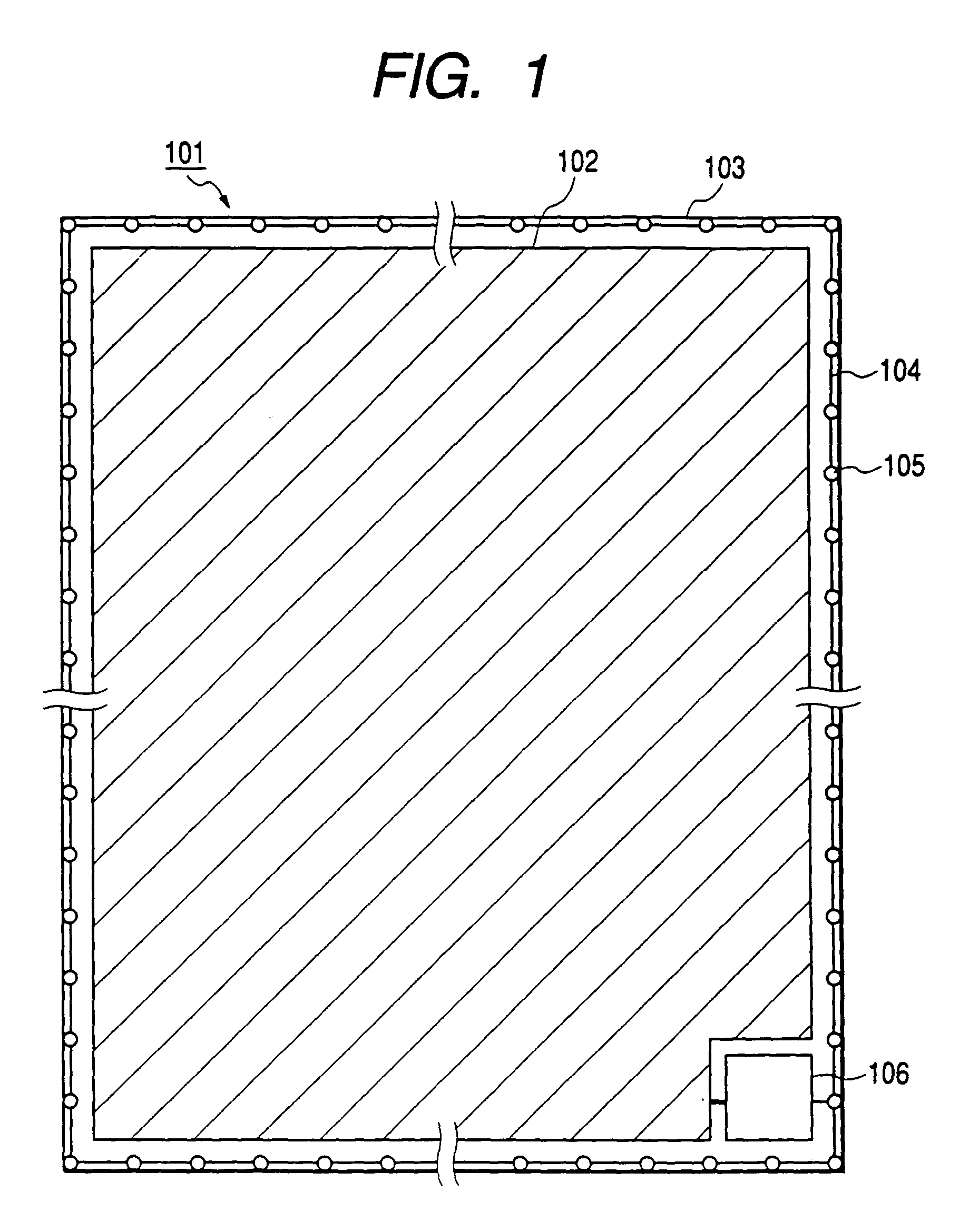
[0091]FIG. 1 is a layout drawing showing a photovoltaic power generation system 101 of the present invention, which has a restricted area 103 including an area 102 where solar cell modules are installed, a means 104 for preventing an intruder from intruding into the restricted area 103, intruder detecting means 105 mounted on the means 104 for preventing the intrusion of intruder, and a building 106 in which devices necessary for the photovoltaic power generation system 101 are located.

[0092]Located inside the building 106 are a junction box for connecting solar cell strings in parallel, an inverter for converting a dc power generated by the solar cell modules, to an ac power, and an electric shock preventing means which is activated by a signal outputted when the intruder detecting means 105 detects an intruder. This photovoltaic power generation system is ...

second embodiment

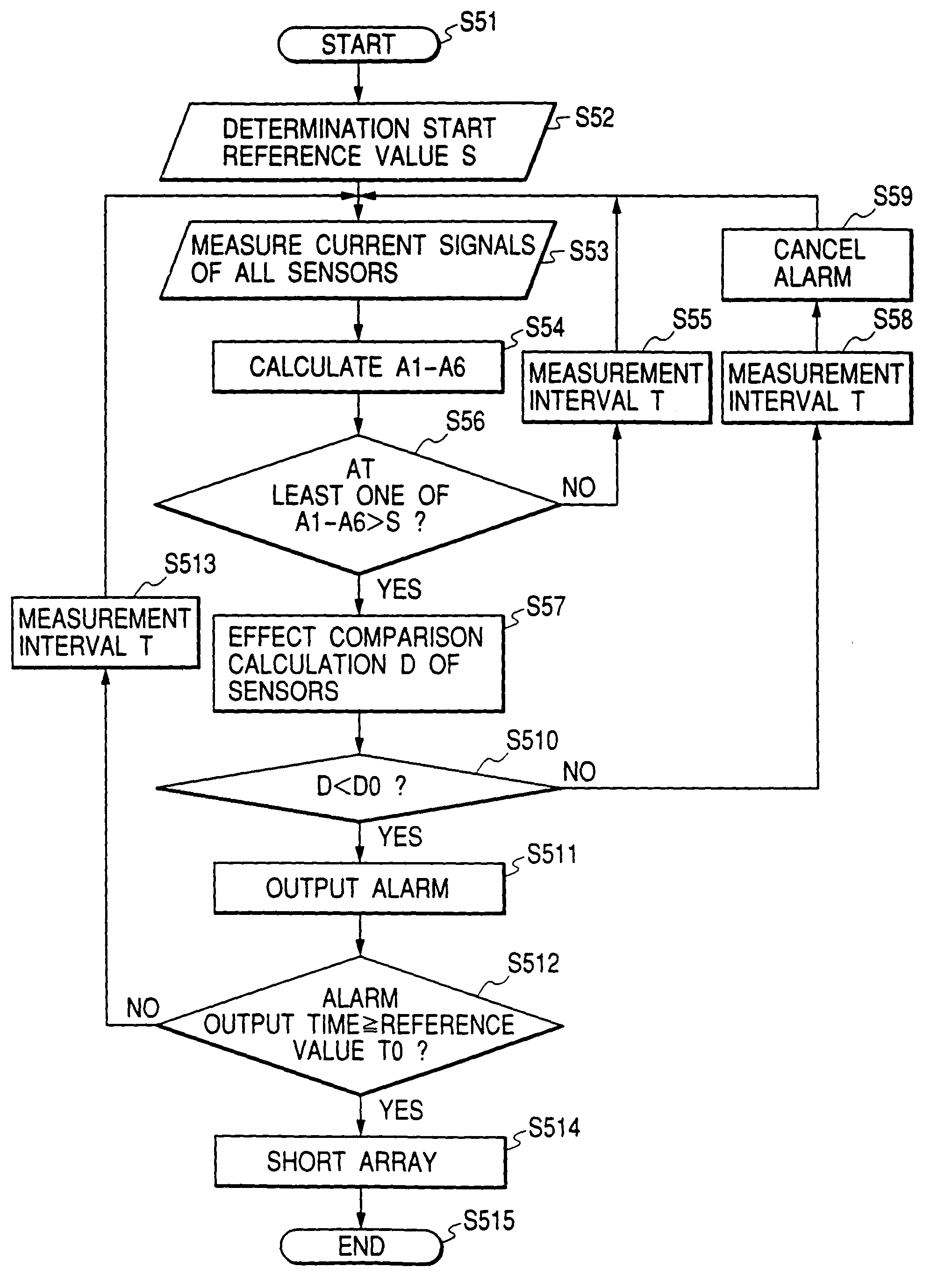
[0105]The second embodiment presents an embodiment of a control method of photovoltaic power generation apparatus (photovoltaic power generation system) according to the present invention.

[0106]FIG. 14 is a block diagram of a photovoltaic power generation apparatus (photovoltaic power generation system) according to the second embodiment and FIG. 15 a block diagram of a roof configuration on which the photovoltaic power generation system is installed.

[0107]In the photovoltaic power generation system according to the present embodiment, each solar cell string (11a to 11c) is composed of sixteen solar cell modules connected in series, and a solar cell array 11 is composed of three solar cell strings connected in parallel and is laid on a roof 21 of a building.

[0108]The positive terminal and negative terminal of each solar cell string (11a to 11c) are guided to a switch 13 for photovoltaic power generation system and a reverse current preventing diode 14 is provided in positive wires. ...

third embodiment

[0114]The third embodiment presents another embodiment of the control method of the photovoltaic power generation apparatus (photovoltaic power generation system) according to the present invention. In the present embodiment the components substantially identical to those in the second embodiment will be denoted by the same reference symbols and detailed description thereof will be omitted.

[0115]In the photovoltaic power generation system of the present embodiment, the sensors (12a to 12n) are not laid only around the solar cell array, but also laid around the string units, as shown in FIG. 19 to FIG. 21, based on the structure of the photovoltaic power generation system of the second embodiment. Then, the short-circuit condition, described in the second embodiment, is modified herein so that a short circuit is established for only a string corresponding to a sensor judged as detecting a human shadow, different from the condition that a short circuit is established for the array of ...


PUM


Abstract

There are provided a restricted area including an area in which solar cell modules are installed, a preventer for preventing intrusion of an intruder into the restricted area, and a detector capable of detecting the intrusion of the intruder into the restricted area, and a predetermined electric shock preventer is activated by a signal outputted from the detector upon detection of the intruder to prevent the intruder from receiving an electric shock.

Description

[0001]This is a divisional application of application Ser. No. 09 / 893,639, filed Jun. 29, 2001, now U.S. Pat. No. 6,653,549.BACKGROUND OF THE INVENTION[0002]1. Field of the Invention[0003]The present invention relates to photovoltaic power generation systems and methods of controlling such photovoltaic power generation systems. More particularly, the present invention concerns photovoltaic power generation systems that are constructed to prevent an intruder, who is attempting to intrude into a restricted area including an area in which solar cells are installed, from receiving an electric shock, and methods of controlling such photovoltaic power generation systems.[0004]2. Related Background Art[0005]In recent years, awareness of environments is spreading across the world. Among others, serious concerns are exhaustion of fossil fuels and the like and global warming due to CO2 emissions, so that the desire for clean energy is growing increasingly. Attention is thus being directed tow...

Claims


Application Information

Patent Timeline
IPC IPC(8): H01L31/042G08B13/12H01L31/048
CPCG08B13/128H01L31/02021H01L31/048Y10S136/29Y02E10/50
Inventor MATSUSHITA, MASAAKITAKABAYASHI, AKIHARUMORI, MASAHIROSHIOMI, AYAKOLIM, CHINCHOUMUKAI, TAKAAKI
Owner CANON KK
Why Eureka
Try Eureka