
Interferometer spectrometer with reduced alignment sensitivity

Inactive Publication Date: 2007-01-09
INLIGHT SOLUTIONS
View PDF25 Cites 16 Cited by
  • Summary
  • Abstract
  • Description
  • Claims
  • Application Information

AI Technical Summary

Benefits of technology

[0015]The interferometer spectrometer of the present invention reduces alignment sensitivity of the critical components without compromising performance or increasing manufacturing costs. Specifically, as compared to the Michelson interferometer, the interferometer of the present invention does not produce tilt error due to relative tilting of the components. As compared to the modified Michelson interferometer utilizing retroreflectors, the interferometer spectrometer of the present invention greatly reduces shear error due to tilting or lateral movement of any of the components. In addition, as compared to the Jamin interferometer, the interferometer spectrometer of the present invention provides a much larger FOV. Further, as compared to the component group rotation interferometers, the interferometer spectrometer of the present invention eliminates tilt and shear sensitivity of the individual components, as opposed to groups of components, thereby providing a more stable design with less complex and lower-cost component mounting techniques. Further yet, as compared to prior art interferometer spectrometers that are field-widened, the interferometer spectrometer of the present invention is field-widened without introducing the possibility of tilt and / or shear error.
[0016]The present invention overcomes the disadvantages of the prior art by providing an interferometer spectrometer that has reduced alignment sensitivity. In particular, variations in relative alignment (angular or translational displacement) do not adversely affect the parallelism (i.e., tilt error) of the recombined output ray pair, and thus do not result in calibration error. In addition, translational variations in relative alignment do not change the separation (i.e., shear error) of the output ray pair, and thus do not result in calibration error. Furthermore, rotational variations in relative alignment produce very little separation (i.e., shear error) of the output ray pair, and thus reduce sensitivity to mounting alignment and stability tolerances as compared to a Michelson interferometer with cube-corner or “cat's-eye” retroreflectors. The reduced alignment sensitivity may be accomplished by utilizing simple planar components that are common to both light paths. The reduced alignment sensitivity and simplicity in design provides a more compact and more robust interferometer, with reduced manufacturing costs associated therewith.
[0020]In yet another exemplary embodiment of the present invention, the light source for an interferometer spectrometer produces an elliptical angular subtense. The elliptical angular subtense light source of the present invention provides an interferometer spectrometer having an increased throughput relative to an interferometer utilizing a light source of circular angular subtense. The light source may include a single collimator lens or an array of collimators lenses each having an array of transmitting fibers disposed adjacent an array of receiving fibers. The array of collimator lenses provides a more compact design than a single circular collimator lens of the same area, and is suitable for single channel or multi-channel use.

Problems solved by technology

Furthermore, rotational variations in relative alignment produce very little separation (i.e., shear error) of the output ray pair, and thus reduce sensitivity to mounting alignment and stability tolerances as compared to a Michelson interferometer with cube-corner or “cat's-eye” retroreflectors.

Method used


Image

  • Interferometer spectrometer with reduced alignment sensitivity
  • Interferometer spectrometer with reduced alignment sensitivity
  • Interferometer spectrometer with reduced alignment sensitivity

Examples


Embodiment Construction

[0028]The following detailed description should be read with reference to the drawings in which similar elements in different drawings are numbered the same. The drawings, which are not necessarily to scale, depict illustrative embodiments and are not intended to limit the scope of the invention.

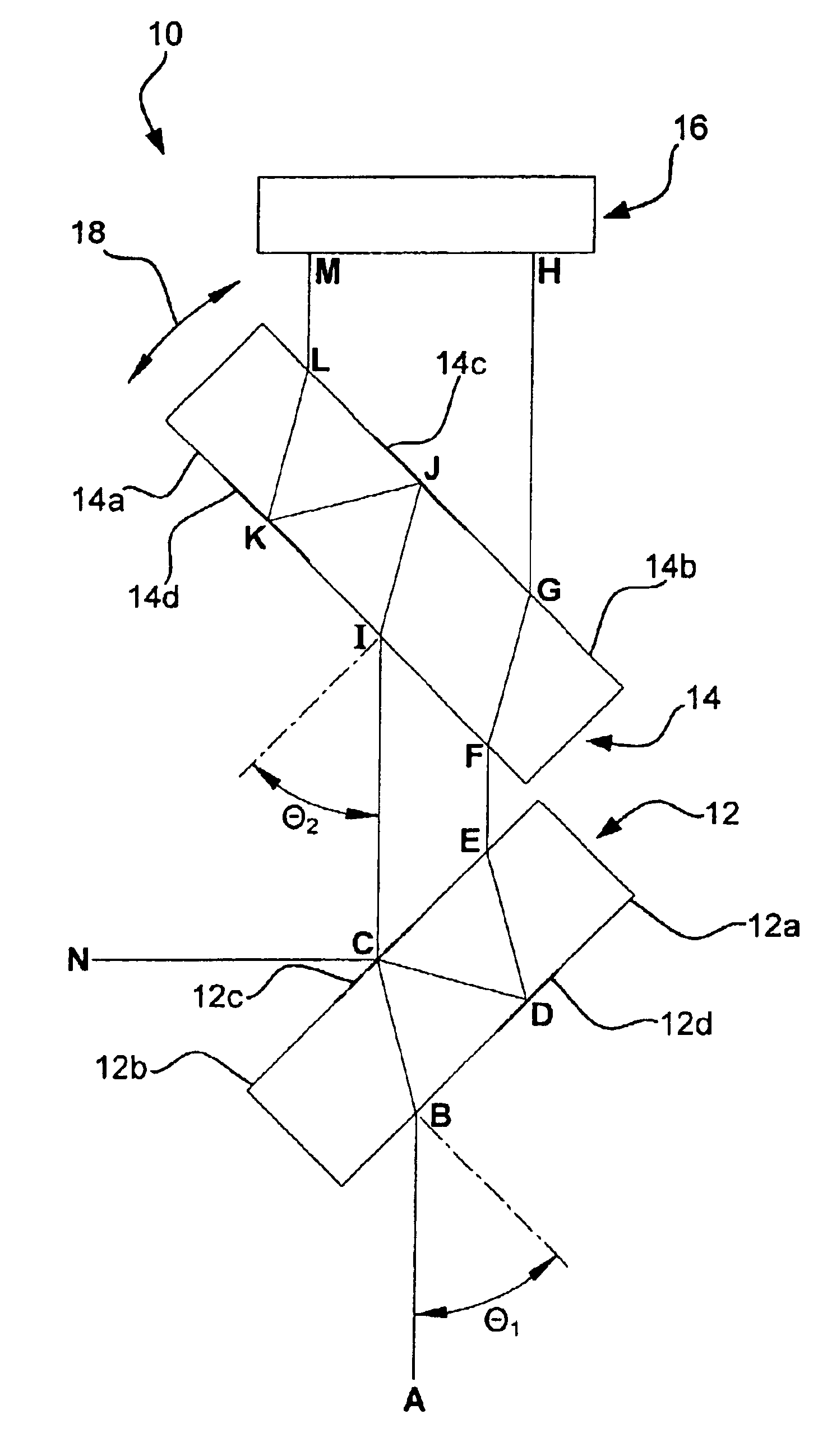
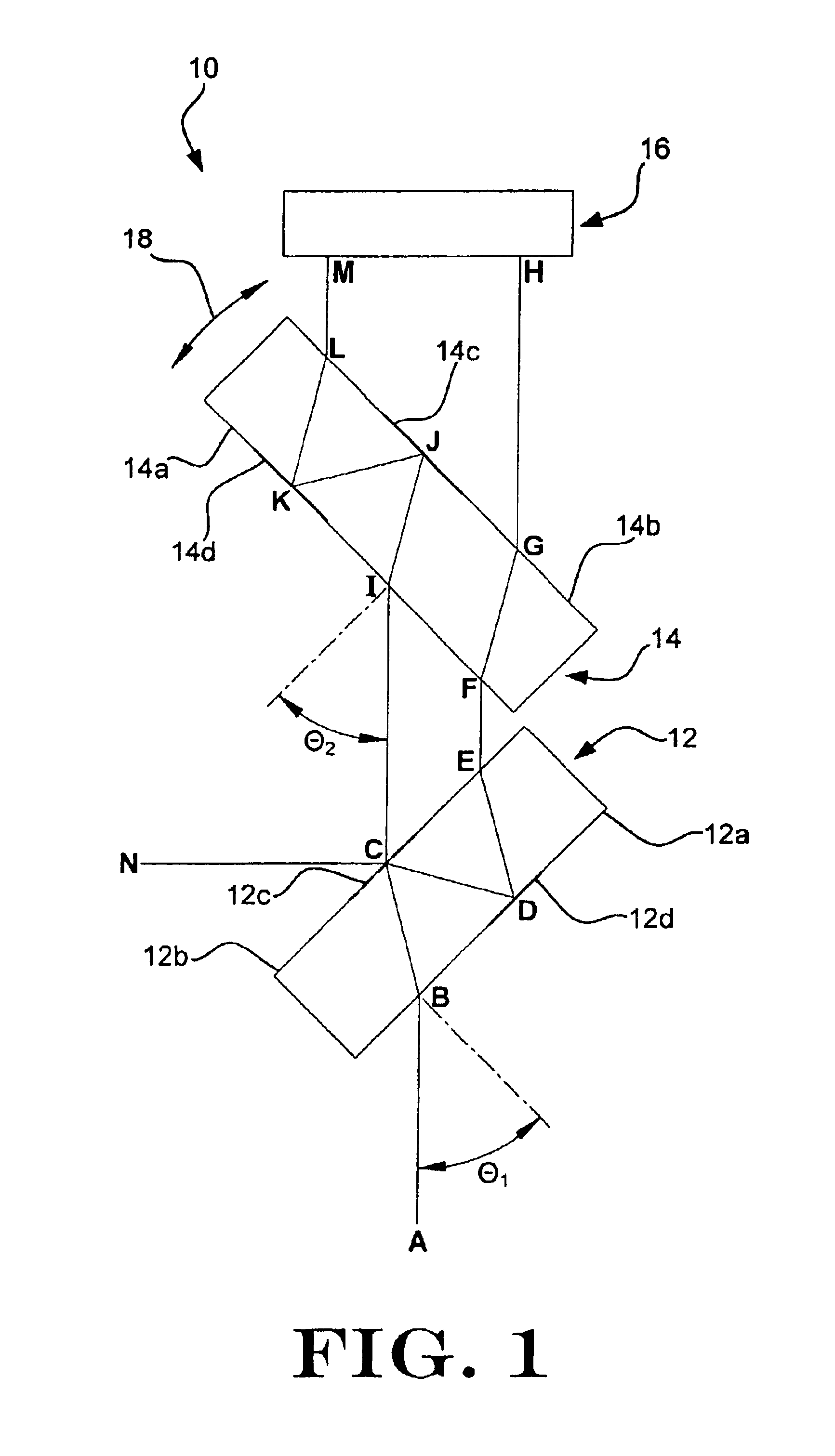
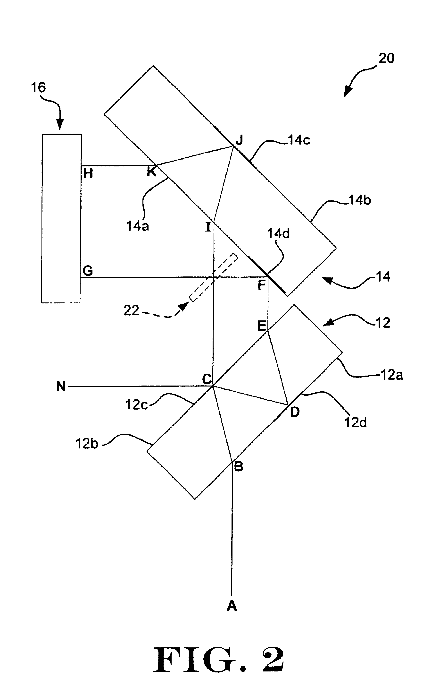
[0029]Refer now to FIG. 1, which illustrates a schematic diagram of an interferometer 10 for use as an interferometer spectrometer, particularly a Fourier transform spectrometer. The interferometer 10 provides a compact and stable design that is relatively insensitive to small alignment errors of the various components. Such a compact and stable design has been shown to be particularly useful when incorporated into a spectrometer used for near infrared non-invasive measurement of blood glucose and other blood analytes in humans, as described in Messerschmidt '530 and Robinson '132, the entire disclosures of which are hereby incorporated by reference. Although described with reference to an i...


PUM


Abstract

An interferometer spectrometer that has reduced alignment sensitivity is described herein. Parallelism of an output ray pair formed by a single input ray is not affected by variations in relative alignment of the components. In comparison to other compensated interferometer designs, lateral separation errors in the output ray pair due to optical component misalignment are reduced. The reduced alignment sensitivity may be accomplished by utilizing simple planar components that are common to both light paths. The reduced alignment sensitivity and simplicity in design provides a more compact and more robust interferometer, with reduced manufacturing costs associated therewith. An elliptical field of view light source that utilizes an array of collimator lenses is also described. The light source provides a more compact design than a single circular collimator lens of the same area, and is suitable for single channel or multi-channel use.

Description

[0001]This application is a continuation of U.S. patent application Ser. No. 09 / 415,600, filed Oct. 8, 1999 now U.S. Pat. No. 6,504,614.FIELD OF THE INVENTION[0002]The present invention is generally related to interferometers. Specifically, the present invention is related to interferometers for use as spectrometers, such as Fourier transform spectrometers.BACKGROUND OF THE INVENTION[0003]Interferometers have historically enjoyed a wide variety of applications for analyzing material properties. For example, as incorporated in a Fourier transform spectrometer, an interferometer may be used in the medical field to detect and measure various constituents of body tissues and fluids. Interferometer spectrometers are particularly useful in the medical field because they allow for relatively non-invasive measurement techniques, as compared to prior art techniques which require tissue and / or fluid sampling by physically removing the sample from the patient.[0004]The ability to perform relat...

Claims


Application Information

Patent Timeline
IPC IPC(8): G01B9/02G01J3/453G01J3/45
CPCG01J3/453
Inventor MESSERSCHMIDT, ROBERT G.ABBINK, RUSSELL E.
Owner INLIGHT SOLUTIONS
Learn More