Heat sink and method for its production

a heat sink and heat sink technology, applied in the field of heat sinks, can solve the problems of increasing size, thickness, etc., and the heat sink cannot be suitable for some of the latest semiconductor devices, and the size of the heat sink is further small, so as to improve the resistance of the heat sink to pressure, improve the cooling performance, and increase the flow amount of coolant

Active Publication Date: 2007-01-09
TECNISCO +1
View PDF21 Cites 8 Cited by
  • Summary
  • Abstract
  • Description
  • Claims
  • Application Information

AI Technical Summary

Benefits of technology

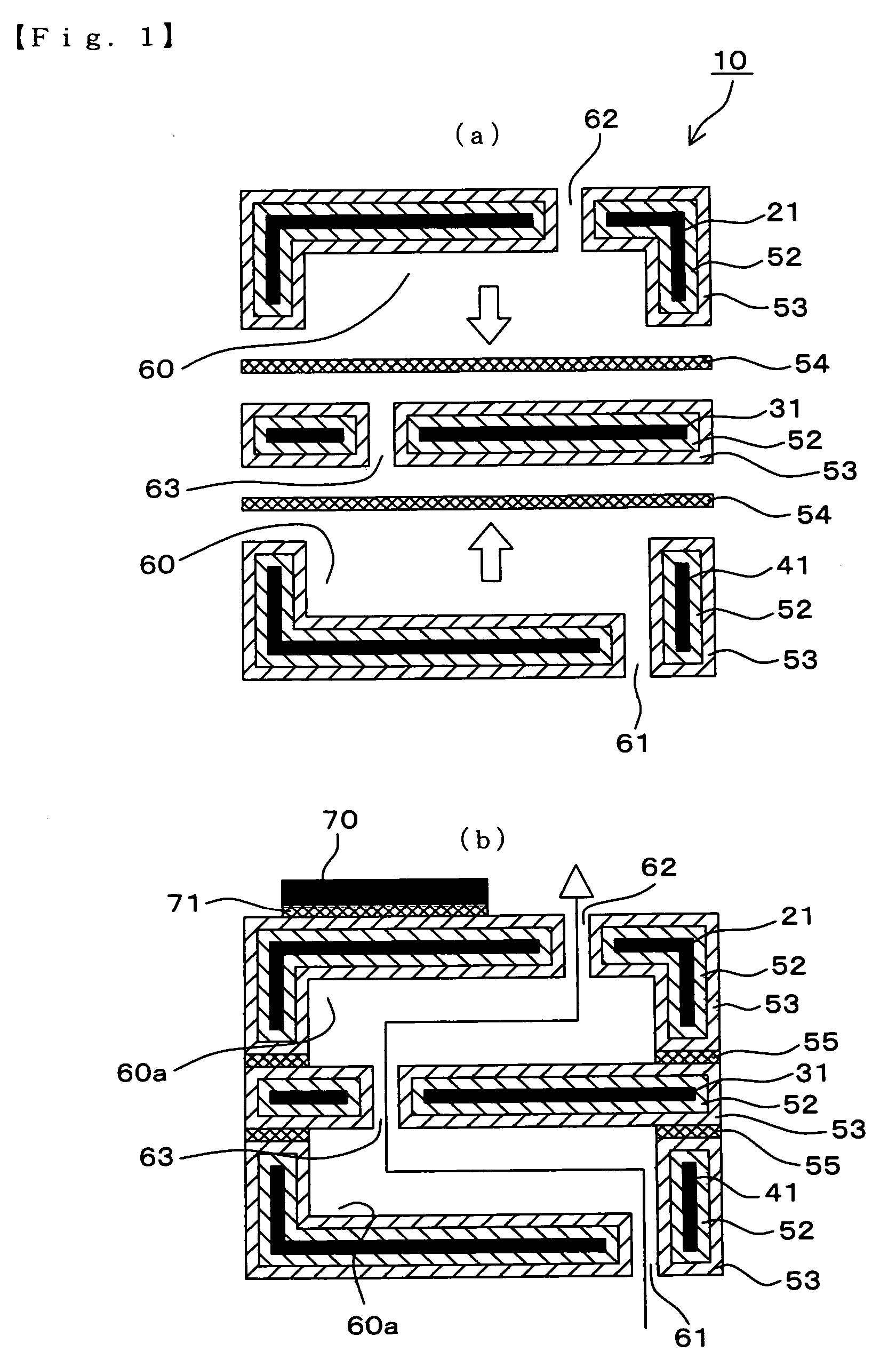
[0014]According to the present invention, a layer of Au and / or Au—Sn alloy, metals of which are both excellent in the resistance against corrosion, is formed as a coating or a bond layer on the surfaces including inner surfaces of the bonded base members. Such layer keeps inner surfaces of the bonded base members from being in contact with a cooling medium, whereby it is possible to obtain a heat sink that is resistible against the corrosion or erosion-corrosion or electrolytic etching occurring inside the heat sink.
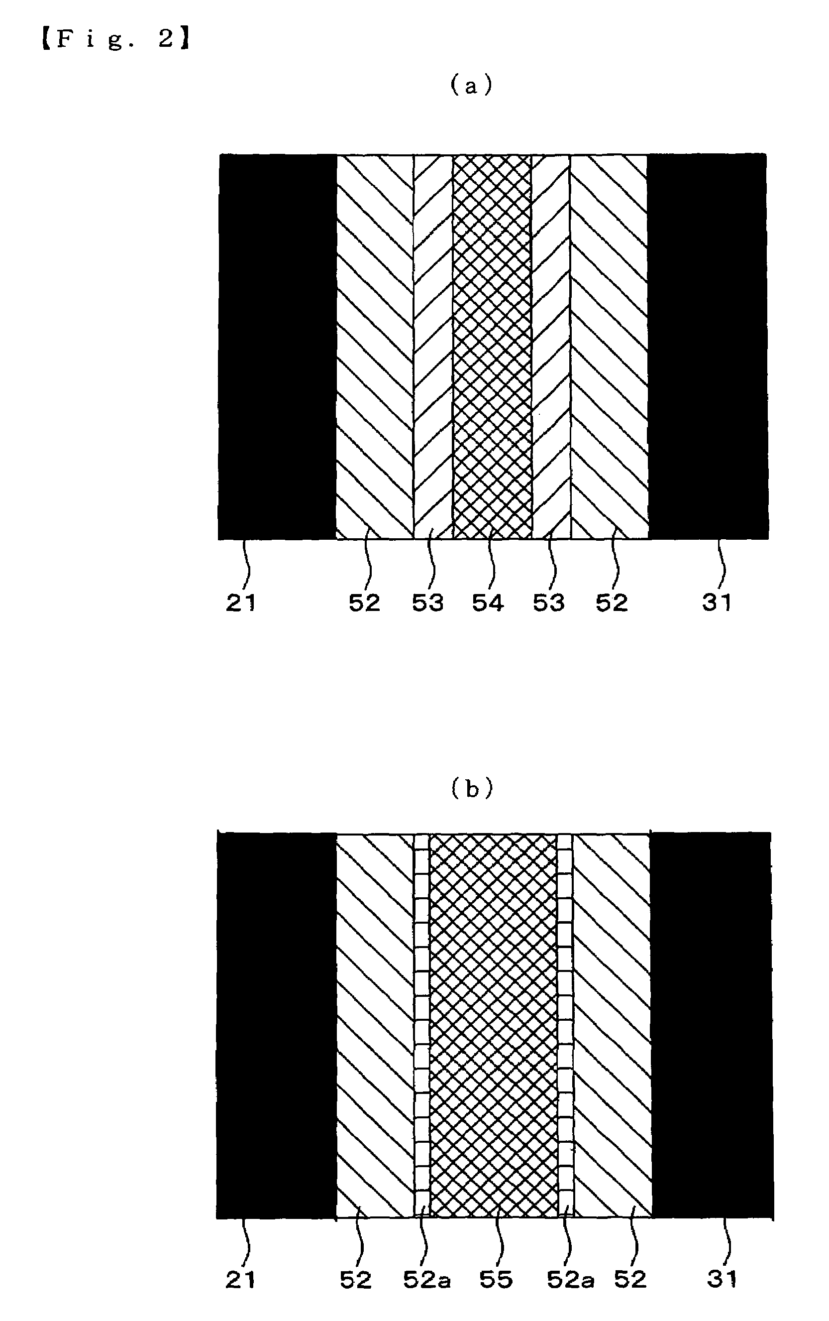
[0030]By conducting the bonding with a solder under the above-mentioned conditions, the solder of Sn or Au—Sn alloy and the coating layer of Au can be sufficiently diffused at the time of forming bonding between the base members. Further, excessive temperature, pressure, or the like, which influences on the qualities of base members and / or the coating layer of Ni, can be avoided, whereby a highly reliable heat sink can be produced.

Problems solved by technology

While the capabilities of the heat sink being further improved, there is a tendency for it to increase in size, thickness, etc., and such heat sink cannot be suitable for some of recent semiconductor devices and the like that become further small in size.
In such an instance, however, corrosion products such as verdigris are formed during a long time circulation of the coolant.
The corrosion products cause clogging, and thus lower the flow amount of the coolant that is going through the coolant.
Such reduction of the flow amount remarkably decreases the cooling performance of the heat sink.
The result from such electrolytic etching is the deformation or clogging of the flow path, further resulting in the reduction of the flow amount of the coolant that is going through the heat sink.
In complementing of the reduction of the flow amount by raising the liquid pressure or the like, such pressure often damages the inner surfaces of the heat sink, causing liquid leakage, etc.
However, it has been difficult to make a precise coating in an appropriate thickness on the surfaces of the base members creating the interspace 150, in which the coolant flows, so that area of the cross section of the flow path would be in constant shape.

Method used


Image

  • Heat sink and method for its production
  • Heat sink and method for its production
  • Heat sink and method for its production

Examples


example 1

[0062]Using the members as shown in FIG. 5, a heat sink 90 of the present invention was produced. This heat sink 90 was constituted by a first base member 91, a second base member 92 and a third base member 93, which are made of a copper plate-like member of 20 mm in width, 11 mm in height and 0.5 mm in thickness. Inside the respective base members, paths for a coolant are defined.

[0063]Namely, the first base member 91 is provided with a half etching portion 91a as a path and a rib 91c for guiding the flow of the coolant, and further an aperture portion 91b. The second base member 92 is provided with a rectangular aperture portion 92a as a path and an aperture portion 92c, and further an aperture portion 92b. The third base member 93 is provided with a half etching portion 93a as a path and an aperture portions 93d and 93c, and further a rib 93e for guiding the flow of the coolant, and furthermore an aperture portion 93b.

[0064]As mentioned above, on the surfaces of the respective b...


PUM

PropertyMeasurementUnit
melting temperatureaaaaaaaaaa
melting pointaaaaaaaaaa
pressureaaaaaaaaaa

Abstract

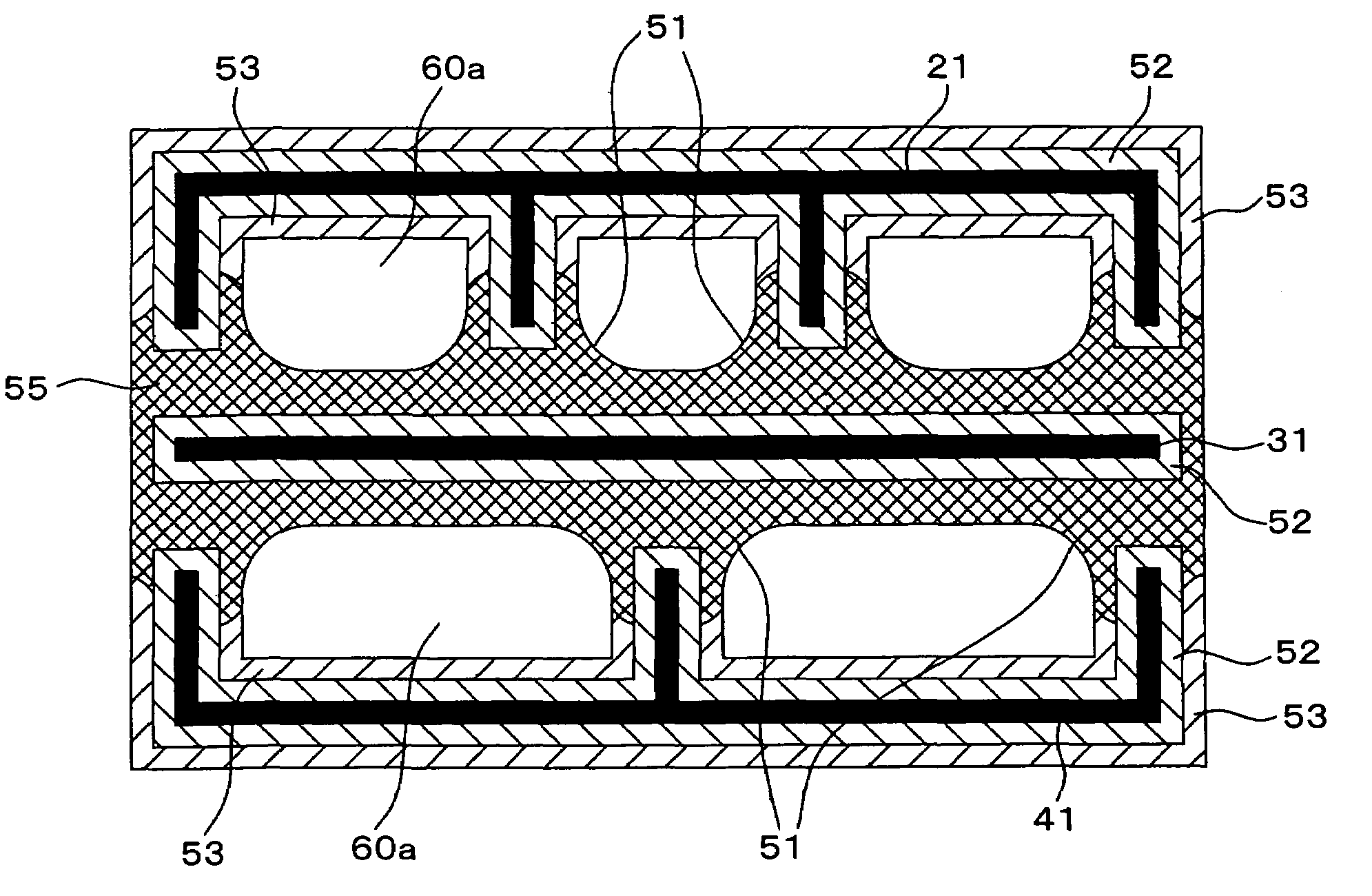
The present invention provides a liquid-cooling type heat sink which has a high pressure-resistibility and is resistible against the corrosion or erosion-corrosion or electrolytic etching, and a method for its production.The heat sink of the present invention comprises plural base members 21, 31 and 41, the base member being each in plate or block-shape, the base member each having paths 60 shaped on one or both sides of surfaces thereof, and the base members being bonded to each other, wherein a communicating flow path 60a including path 60, through holes 61, 62, and 63, is formed for a cooling medium to flow in and out. The base members are bonded to each other with a solder layer 54 made of Au—Sn alloy or Sn, while a coating layer of Au 53 is formed on each of the inner surfaces of the bonded base members. At the time of making a bond between the base members, the coating layer of Au 53 and the solder layer 54 are diffused to each other, resulting in formation of a bond layer of alloy 55 containing at least 91 wt % of Au and at most 9 wt % of Sn.

Description

FIELD OF THE INVENTION[0001]The present invention relates to a heat sink used for dissipation of heat from heat-generating devices, such as a semiconductor device, for example, a semiconductor, laser diode, and a method for its production.BACKGROUND[0002]The semiconductor device, such as a semiconductor laser diode, which has been used in various fields, makes increased heat generation during operation, and thus heat sinks are generally used for cooling it.[0003]The development of high performance semiconductor devices and the like in recent years, such as one with high brightness and / or high output power, requires higher cooling properties in a heat sink. The durability of such cooling properties are also requires in a heat sink, such that the heat sink stably performs its capability of dissipation of heat from heat-generating devices, such as a semiconductor device, during its long lifetime. To meet these demands, various types of heat sinks are developed.[0004]While the capabilit...

Claims


Application Information

Patent Timeline
Patent Type & Authority Patents(United States)
IPC IPC(8): H05K7/20H01L23/36H01L23/373H01L23/473
CPCH01L23/473H01L2924/0002H01L2924/00
Inventor YANASE, ATSUSHITAKAHASHI, MASATOKANEDA, YUKIHIRO
Owner TECNISCO
Why Eureka
Try Eureka