

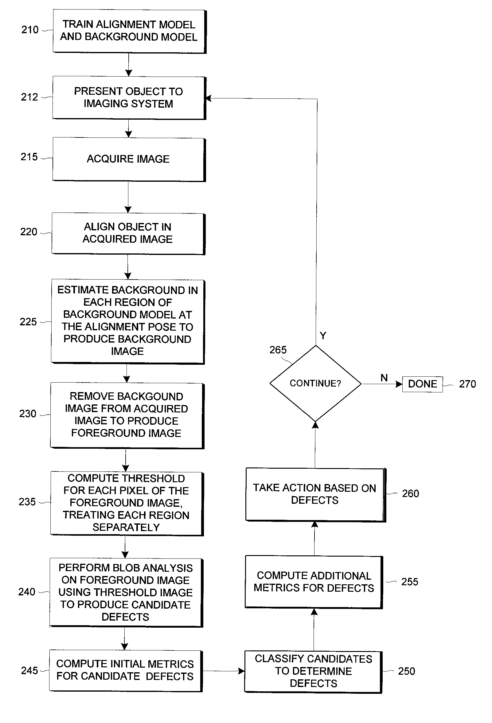
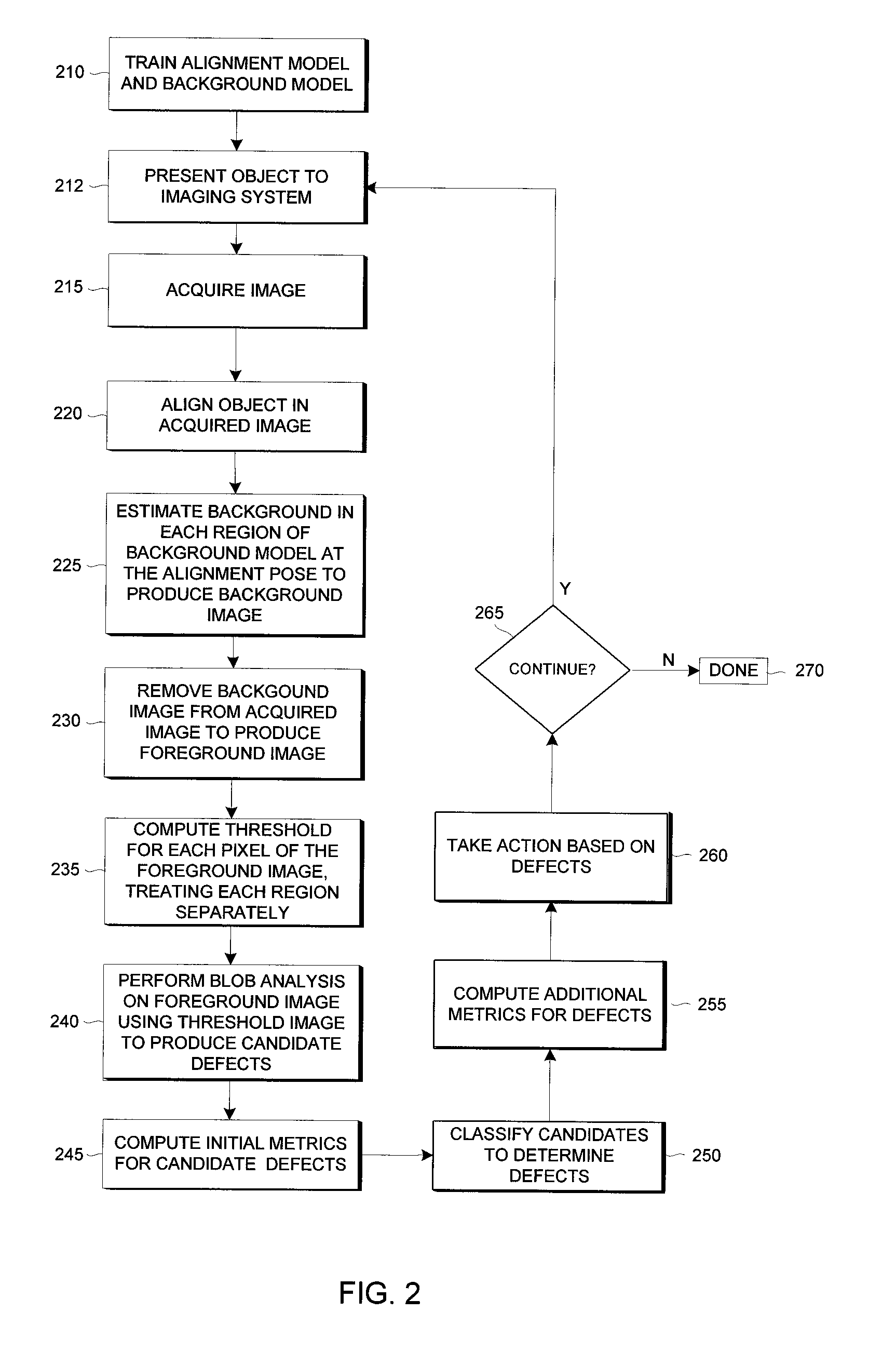
Methods and apparatuses for detecting classifying and measuring spot defects in an image of an object
a technology of image defects and classification, applied in the field of machine vision, can solve problems such as unfavorable deviations, undesirable blemishes within the region between actual object boundaries, and “spot” defect detection, classification and/or measurement, and achieve the effects of improving the accuracy and reliability of results, simple blob analysis, and high image nois
- Summary
- Abstract
- Description
- Claims
- Application Information
AI Technical Summary
Benefits of technology
Problems solved by technology
Method used
Image

Examples
Embodiment Construction
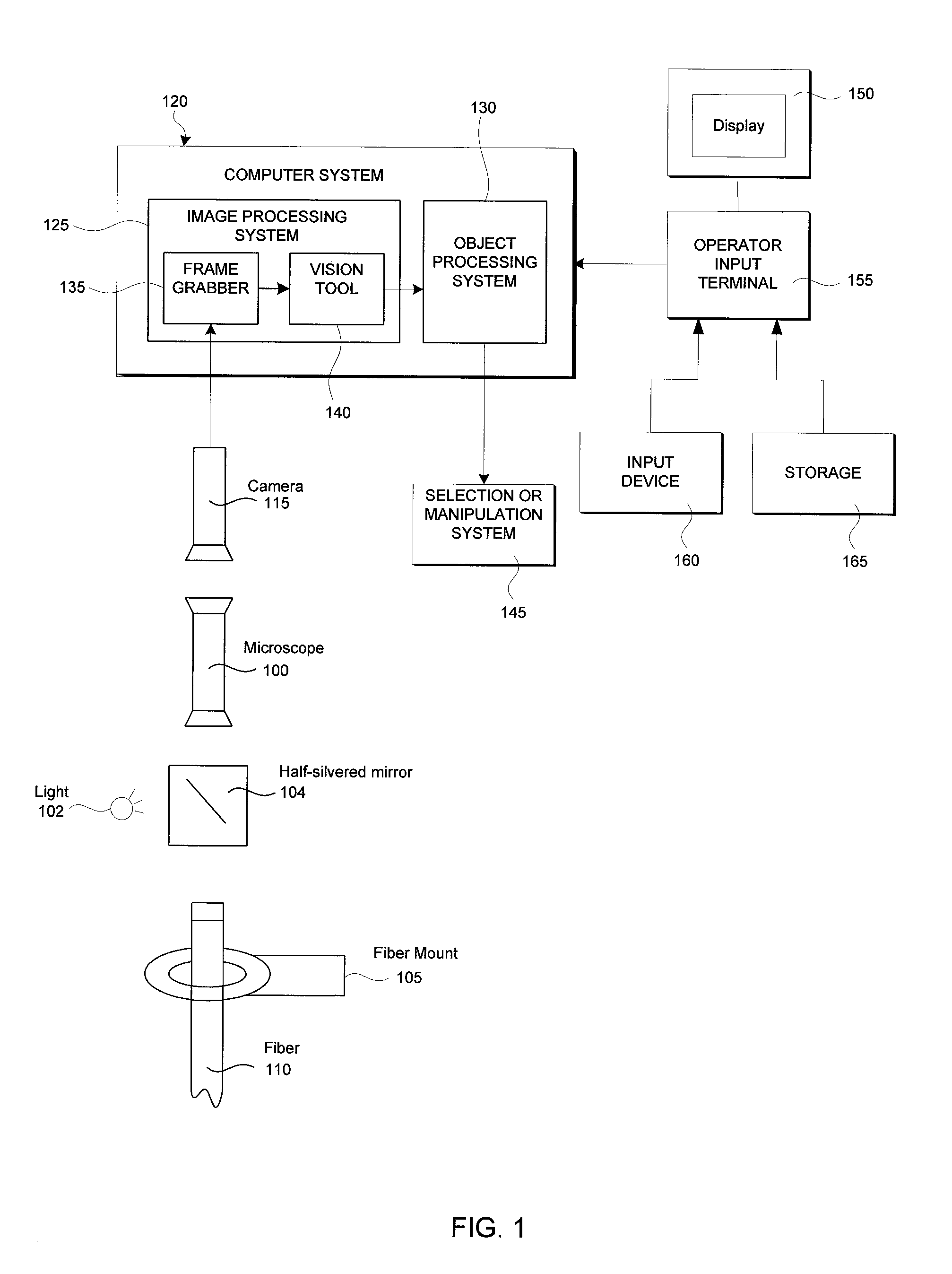
[0051]FIG. 1 illustrates in schematic form an example of a machine vision system that can utilize the process of the present invention. The example system demonstrates the inspection of the end-face of an optical fiber, but this example is merely illustrative and not restrictive. In the example system, a fiber microscope 100 examines an optical fiber 110 held in a mounting device 105. The fiber may also be presented to the system by other well-known mechanisms. When a fiber is in the mount, an image stream of the fiber is created by a camera system 115 in a conventional manner. Light is provided by a light source 102, and a half-silvered mirror 104 is used to direct the light onto the fiber end-face while also allowing the fiber end-face to be imaged by the camera 115. Other arrangements of optics and lighting are possible. The image stream created by the camera 115 is provided to a computer system 120 which processes the image according to the method of the present invention.
[0052]...
PUM
| Property | Measurement | Unit |
|---|---|---|
| threshold | aaaaa | aaaaa |
| defect image | aaaaa | aaaaa |
| defect | aaaaa | aaaaa |
Abstract
Description
Claims
Application Information