
Method and apparatus for load sharing in wireless access networks based on dynamic transmission power adjustment of access points

Inactive Publication Date: 2007-01-09
IBM CORP
View PDF7 Cites 120 Cited by
  • Summary
  • Abstract
  • Description
  • Claims
  • Application Information

AI Technical Summary

Benefits of technology

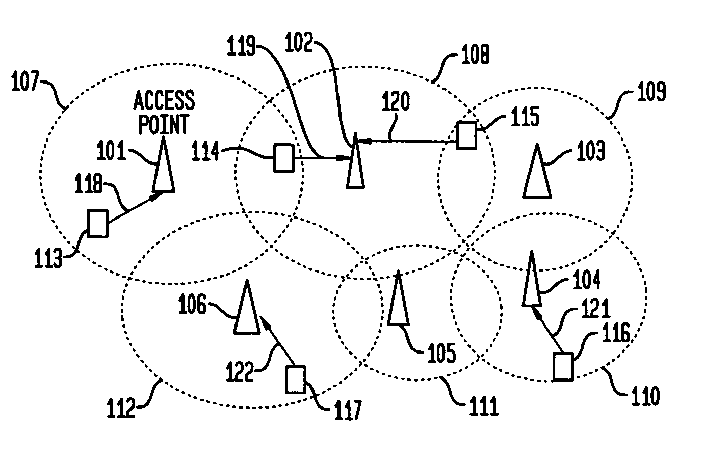
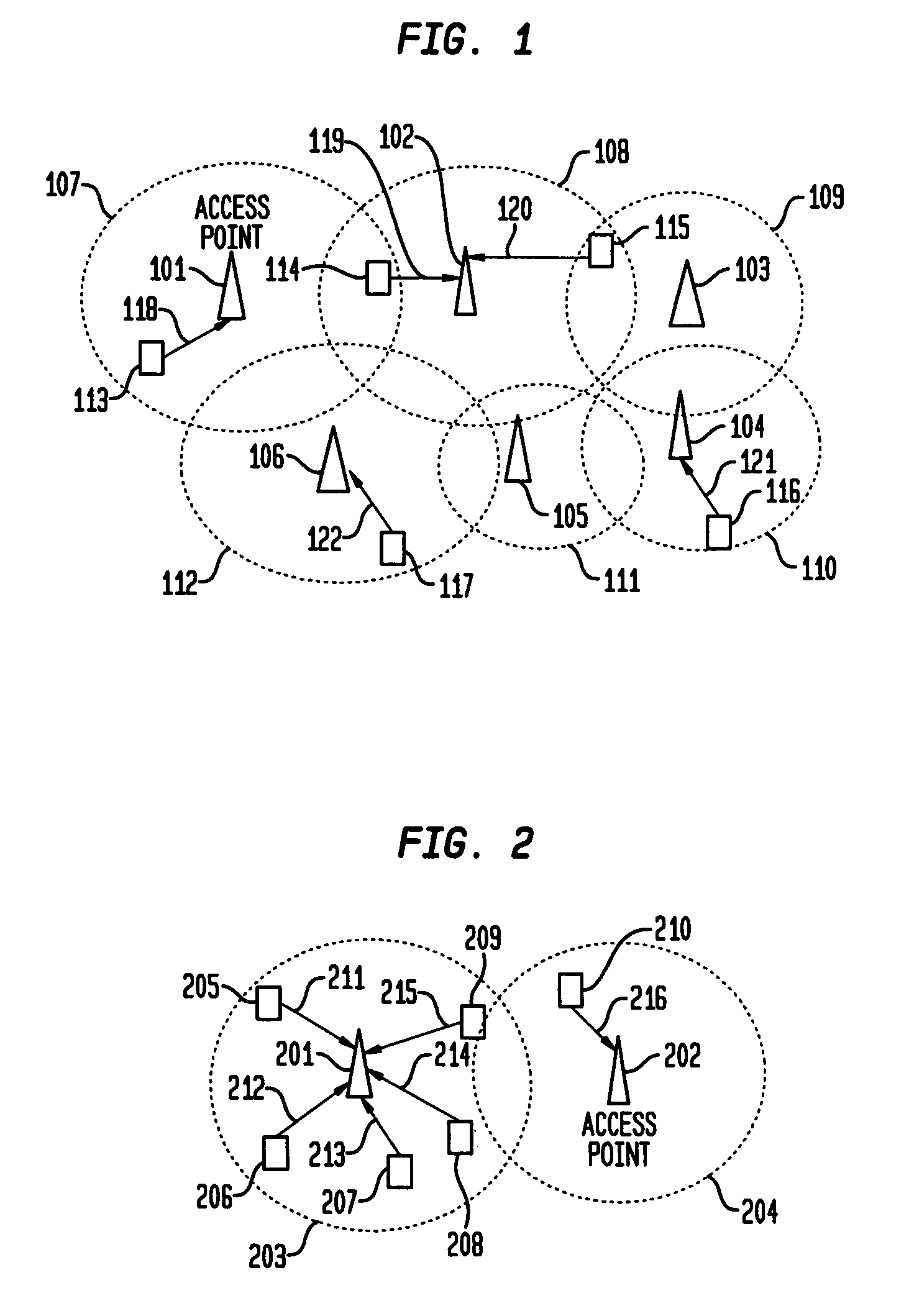
[0018]When a particular cell (or equivalently, AP) gets overloaded, the invention proposes to increase (in a controlled manner) the power level of neighboring access points, such that they increase the area of overlap with the specific cell. As a result of this overlap, a larger number of computing devices find it feasible to access the wired network via alternative APs, thereby shifting a fraction of the load from the current access point to neighboring APs. Alternatively, when a particular cell gets overloaded, the invention proposes a technique by which the associated AP lowers its transmission power, thereby decreasing the footprint of its associated cell. Accordingly, nodes that lie outside the decreased coverage area (but were within the bounds of the original cell footprint) will now be forced to associate with alternative APs, thereby offloading a fraction of the traffic load from the (currently) overloaded access point to suitable alternative APs. Advantageously, the power-adaptation techniques implemented requires no special antenna capabilities, and works in relatively unsophisticated and inexpensive wireless network installations.
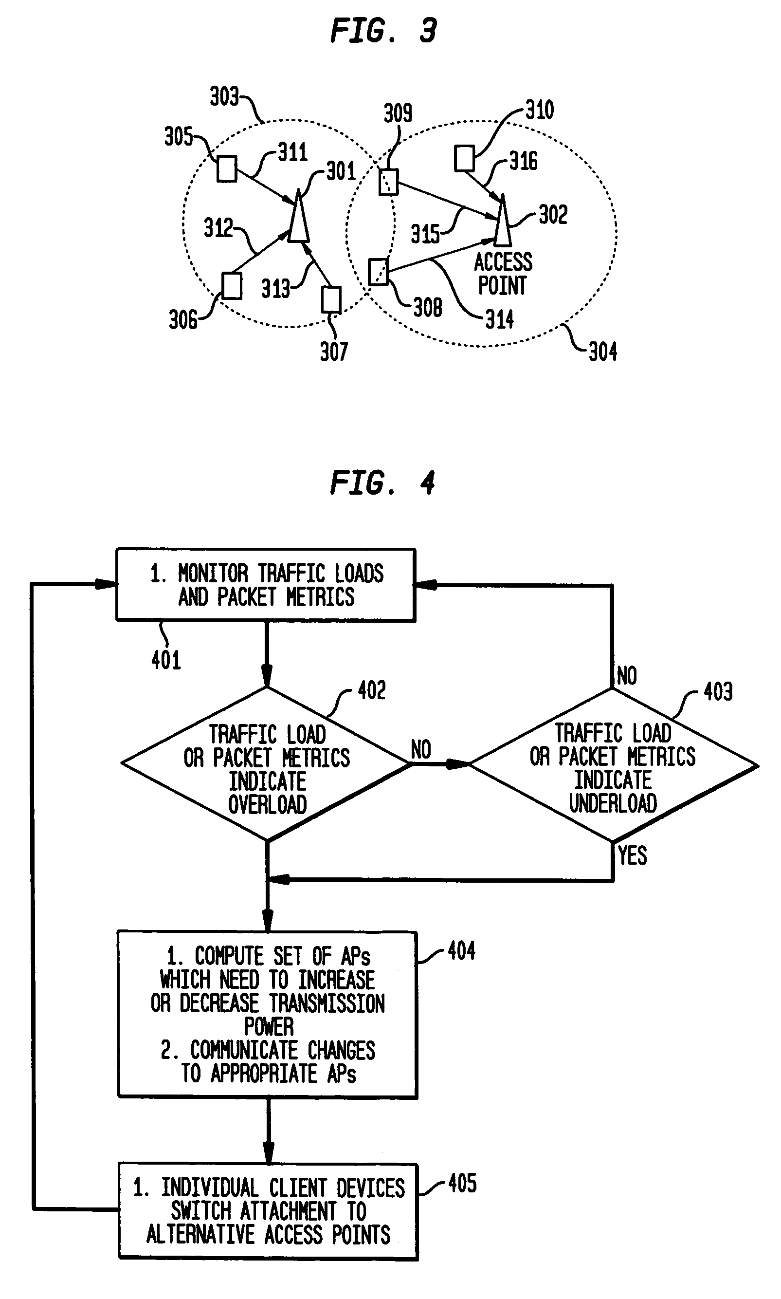
[0021]According to another aspect of the invention, there is provided a centralized entity referred to as a Load Balancing Manager (LBM) that may be implemented in software to adjust the power levels (and hence, footprints) of a collection of APs. By monitoring the load levels on each of the individual APs, the LBM detects when a particular access point is loaded (which may be expressed as a variety of conditions, such as the number of attached users exceeding a threshold, or the volume of traffic exceeding a certain rate, or the processing delay exceeding an acceptable bound). The LBM then instructs neighboring underloaded APs to increase their transmission power level, thereby increasing their area of overlap with the current AP's footprint. As a result of this overlap, one or more wireless devices attached to the current AP may now lie in the footprint of alternative APs; by switching these devices to those APs, the LBM may reduce the traffic load on the current AP to more acceptable levels.

Problems solved by technology

Advantageously, the power-adaptation techniques implemented requires no special antenna capabilities, and works in relatively unsophisticated and inexpensive wireless network installations.

Method used


Image

  • Method and apparatus for load sharing in wireless access networks based on dynamic transmission power adjustment of access points
  • Method and apparatus for load sharing in wireless access networks based on dynamic transmission power adjustment of access points
  • Method and apparatus for load sharing in wireless access networks based on dynamic transmission power adjustment of access points

Examples


Embodiment Construction

[0035]The invention is directed to a new load balancing mechanism that is a member of the Load Adaptation approach. While prior art mechanisms for Load Adaptation rely on explicit signaling (exchange of messages) between the AP and a wireless client node, in effect, instructing it to switch to an alternative AP, even though the wireless node is still within the footprint of the current AP, the load-balancing mechanism according to one embodiment of the present invention, as will be hereinafter described, does not require any such explicit signaling, but instead, forces a target wireless device to switch to another AP, by reducing the footprint of the AP to exclude the wireless device from the new footprint.

[0036]That is, the present invention provides a way in which a set of access points providing wireless cellular coverage use adjustments to their transmission powers to alter the cellular topology in response to excessive traffic loads at certain “hot-spots”. For example, an overl...


PUM


Abstract

A load balancing system and methodology for packet-based wireless cellular networks, whereby wireless access points are dynamically reconfigured by altering their transmission power level to modify their area of coverage. The modification function is based on the localized traffic load or congestion at each individual access point, or the collective load experienced by groups of access points. This modification to the cellular layout is used as an implicit load-balancing technique. When an overloaded access point reduces its coverage area, it forces some wireless client devices that were earlier within its footprint, but no longer within its coverage area, to attach to alternative access points. Similarly, when an underloaded access point increases its coverage area, it provides an opportunity to wireless devices, which were earlier outside its footprint, but now within the expanded coverage area, to switch attachment to this access point. By changing the access point to which a wireless device attaches, the load-levels on the individual access points are indirectly changed.

Description

BACKGROUND OF THE INVENTION[0001]1. Field of the Invention[0002]The present invention relates to computer network connectivity and wireless networking, and particularly, to a cellular wireless access infrastructure, where individual client wireless devices use a set of access point devices as gateway nodes to connect to a wired backbone network.[0003]2. Description of the Prior Art[0004]Wireless access networks are often designed in a cellular fashion, with multiple access points (also called base stations) offering multiple points of attachment to a backbone (e.g., wired) networking infrastructure. Individual wireless client computing devices may connect to the network by attaching to one (or, at least in theory, more) of these access points, as long as they lie within a communication range of the concerned access point(s). The access points (APs) are laid out in cellular fashion, with each access point's area of coverage being defined by an area known as the cell size. The composi...

Claims


Application Information

Patent Timeline
IPC IPC(8): H04Q7/20H04B7/005H04L12/28H04W16/06H04W52/28H04W52/34
CPCH04W16/08H04W52/34H04W52/283H04W36/22
Inventor MISRA, ARCHAN
Owner IBM CORP
Learn More