
Oil/water separator with enhanced in-situ cleaning

a technology of oil/water separator and in-situ cleaning, which is applied in the direction of liquid displacement, vessel construction, separation processes, etc., can solve the problems of labor-intensive separator cleaning and maintenance procedures, and achieve the effect of enhancing in-situ cleaning of plate stacks, convenient assembly and disassembly, and ensuring the quality of oil separation

Inactive Publication Date: 2007-01-16
NAVY CHIEF OF NAVAL RES OFFICE OF COUNSEL DEPT OF THE
View PDF13 Cites 8 Cited by
  • Summary
  • Abstract
  • Description
  • Claims
  • Application Information

AI Technical Summary

Benefits of technology

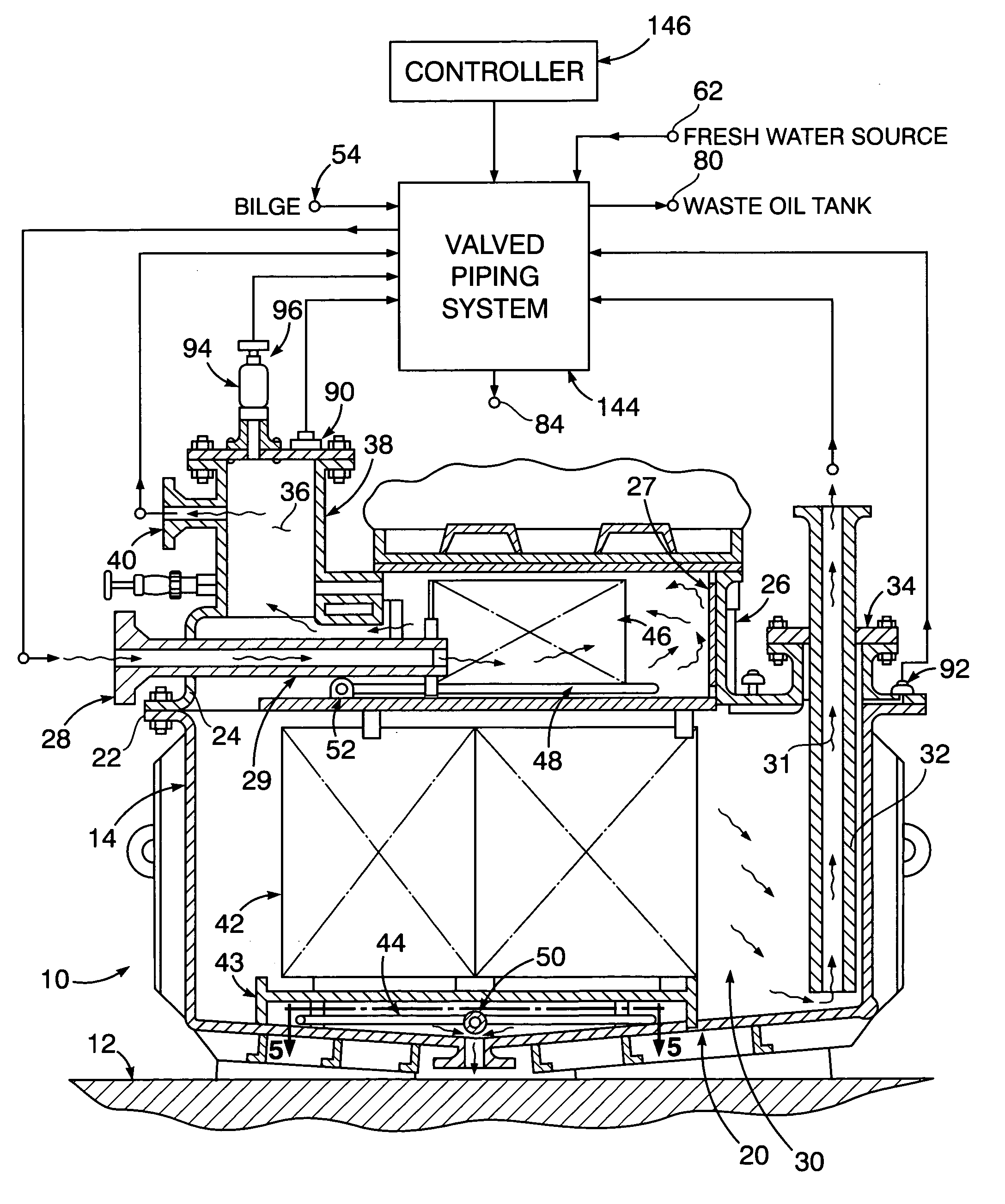
[0004]Pursuant to the present invention, the oil / water separator features separate lower and upper tank chamber sections that are readily assembled and disassembled from each other for installation and replacement of oil separating plate stacks that are respectively positioned within the lower and upper tank sections in overlying relation to in-situ cleaning air sparging arrays therein. A valve control piping system is fixedly positioned on top of the upper tank section of the separator, together with the oil tower within which separated oil is collected and withdrawn for drainage into a waste oil storage tank under computer programmed control of electrically driven valves in the piping system which is also provided with manually controlled valves for selective operational conditioning of the separator. Valve controlled facilities are also provided by the valve control piping system for fresh water clean-up, wastewater treatment and wastewater overboard discharge. Oil separation quantities are accordingly enlarged while in-situ cleaning of the plate stacks is enhanced.

Problems solved by technology

Current procedures for separator cleaning and for maintenance thereof are labor-intensive and also involve exposure of personnel to waste oil and cleansing chemicals utilized.
Furthermore such oil / water separators involve separation limited to small quantities of oil such as 10-gallons per minute (gpm).

Method used


Image

  • Oil/water separator with enhanced in-situ cleaning
  • Oil/water separator with enhanced in-situ cleaning
  • Oil/water separator with enhanced in-situ cleaning

Examples


Embodiment Construction

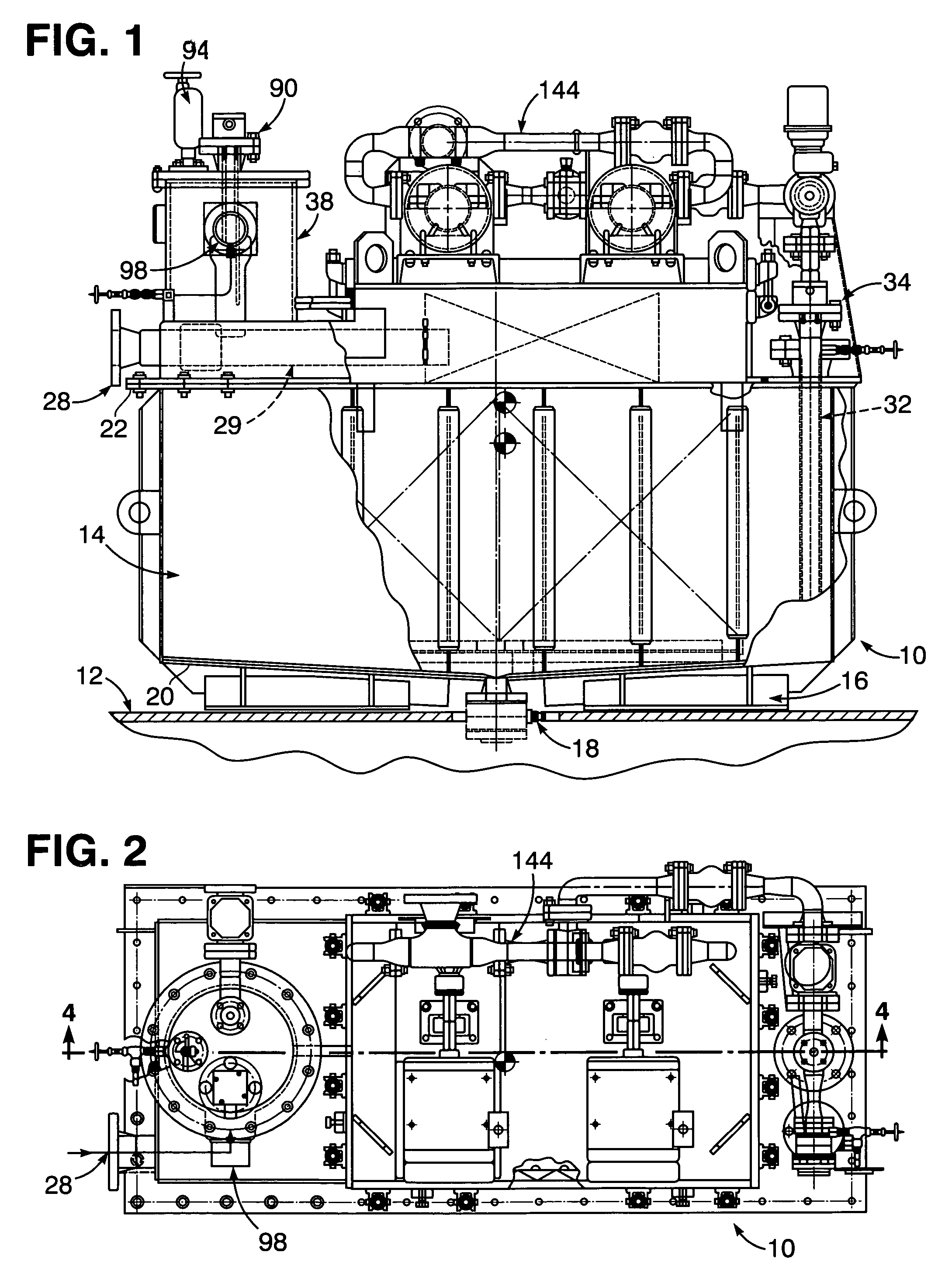
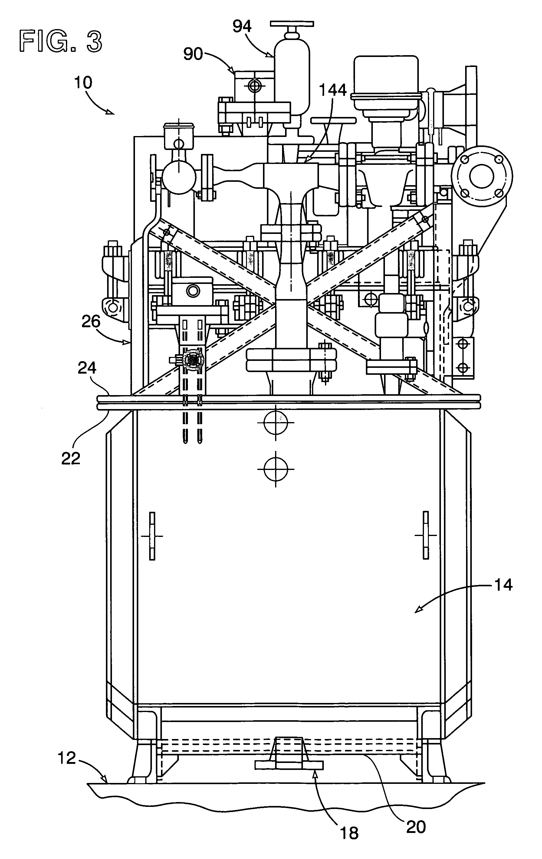
[0014]Referring now to the drawing in detail, FIGS. 1–4 illustrate an oil / water separator 10 with which the subject invention is associated as hereinafter explained. The separator 10 is shown positioned at a suitable location on a support surface 12, within a sea vessel such as a U.S. Naval ship, for in-situ separation therein of oil from an oily wastewater bilge such as seawater. The separator 10 is provided with a cross-sectionally rectangular lower tank chamber section 14 attached to the surface 12 by leg structure assemblies 16, between which a drain fitting 18 extends from a bottom 20 of the lower tank section 14. A gasket flange 22 is connected to and extends peripherally from a top of the lower tank section 14, to which a corresponding flange 24 of an upper tank chamber section 26 is removably attached. An oil / water inlet fitting 28 from which an inlet tube 29 extends is positioned within the upper tank section 26 above the lower tank section 14, through which the wastewater ...


PUM

PropertyMeasurementUnit
Pressureaaaaaaaaaa
Sizeaaaaaaaaaa
Sizeaaaaaaaaaa

Abstract

In-situ cleaning of the bilgewater processing plates of stacks within a treatment tank chamber of a 50-gpm oil / water separator is performed by an injected chemical cleaning agent dispersed by diverted flow of pressurized air introduced into the tank chamber below the plate stacks by emergence of air bubbles from plural branches of an air sparging array system positioned in underlying alignment with crest formations on the processing plates. The air sparging array system consists of an upper and lower tank arrays.

Description

[0001]The present invention relates generally to an oil / water separator with enhanced installational and operational facilities.STATEMENT OF GOVERNMENT INTEREST[0002]The invention described herein may be manufactured and used by or for the Government of the United States of America for governmental purposes without the payment of any loyalties thereon or therefore.BACKGROUND OF THE INVENTION[0003]Oil / water separators with in-situ cleaning of the oil separating plate stacks therein are now generally known in the art as disclosed for example in U.S. Pat. No. 6,659,290 B1 to Lawson et al. Current procedures for separator cleaning and for maintenance thereof are labor-intensive and also involve exposure of personnel to waste oil and cleansing chemicals utilized. Furthermore such oil / water separators involve separation limited to small quantities of oil such as 10-gallons per minute (gpm). It is therefore an important object of the present invention to provide an arrangement for the fore...

Claims


Application Information

Patent Timeline
IPC IPC(8): B01D17/028
CPCB01D17/0205B63B17/06B01D17/0214B01D17/0211
Inventor VEROSTO, STEPHAN J.DIVALENTIN, MARIOFERCHAU, DAVID O.HONAN, MICHAELCITINO, III, J. WILLIAMFRESHCOLN, DAVID E.
Owner NAVY CHIEF OF NAVAL RES OFFICE OF COUNSEL DEPT OF THE
Learn More