Projection system and method

a projection system and projection method technology, applied in the field of projection systems, can solve the problems of reducing the width of color selection, generating a large amount of heat, and emitted many unnecessary infrared and ultraviolet rays, and achieve the effect of small size and light efficiency

Active Publication Date: 2007-01-16
SAMSUNG ELECTRONICS CO LTD
View PDF17 Cites 6 Cited by
  • Summary
  • Abstract
  • Description
  • Claims
  • Application Information

AI Technical Summary

Benefits of technology

[0014]The present invention provides a projection system which may be small in size and may exhibit light efficiency by employing a plurality

Problems solved by technology

They emit many unnecessary infrared rays and ultraviolet rays and generate a great amount of heat, and accordingly necessitate a cooling fan.
But, the cooling pan can cause noise.
Also, the lamp light source has a narrow color spectrum which reduces the width of color selection, degrades color purity, and cannot be stably used because of its short life.
Thus, reducing the size of a projection system is difficult.
Accordingly, an optical system becomes larger, and the yield degrades due to

Method used


Image

  • Projection system and method
  • Projection system and method
  • Projection system and method

Examples


Embodiment Construction

[0032]Reference will now be made in detail to the present preferred embodiments of the present invention, examples of which are illustrated in the accompanying drawings, wherein like reference numerals refer to the like elements throughout. The embodiments are described below in order to explain the present invention by referring to the figures.

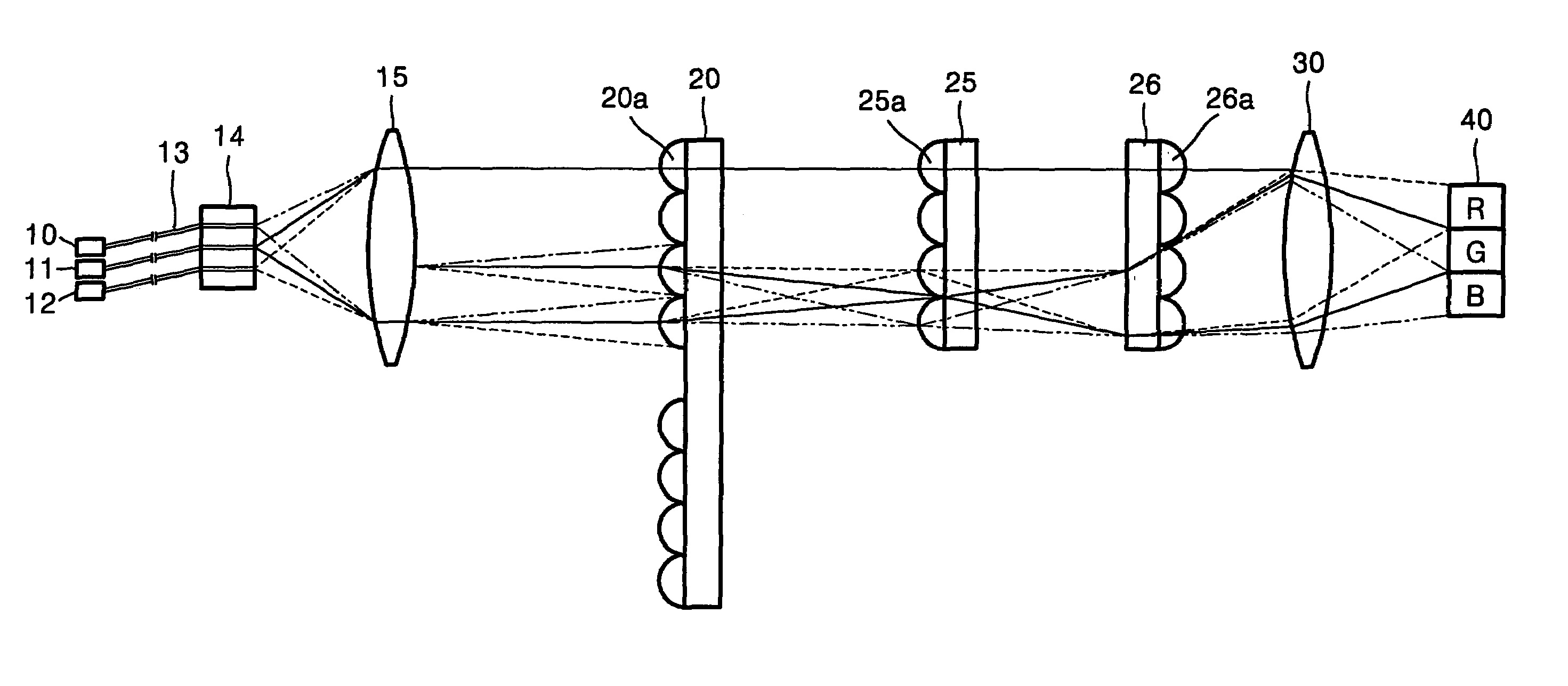
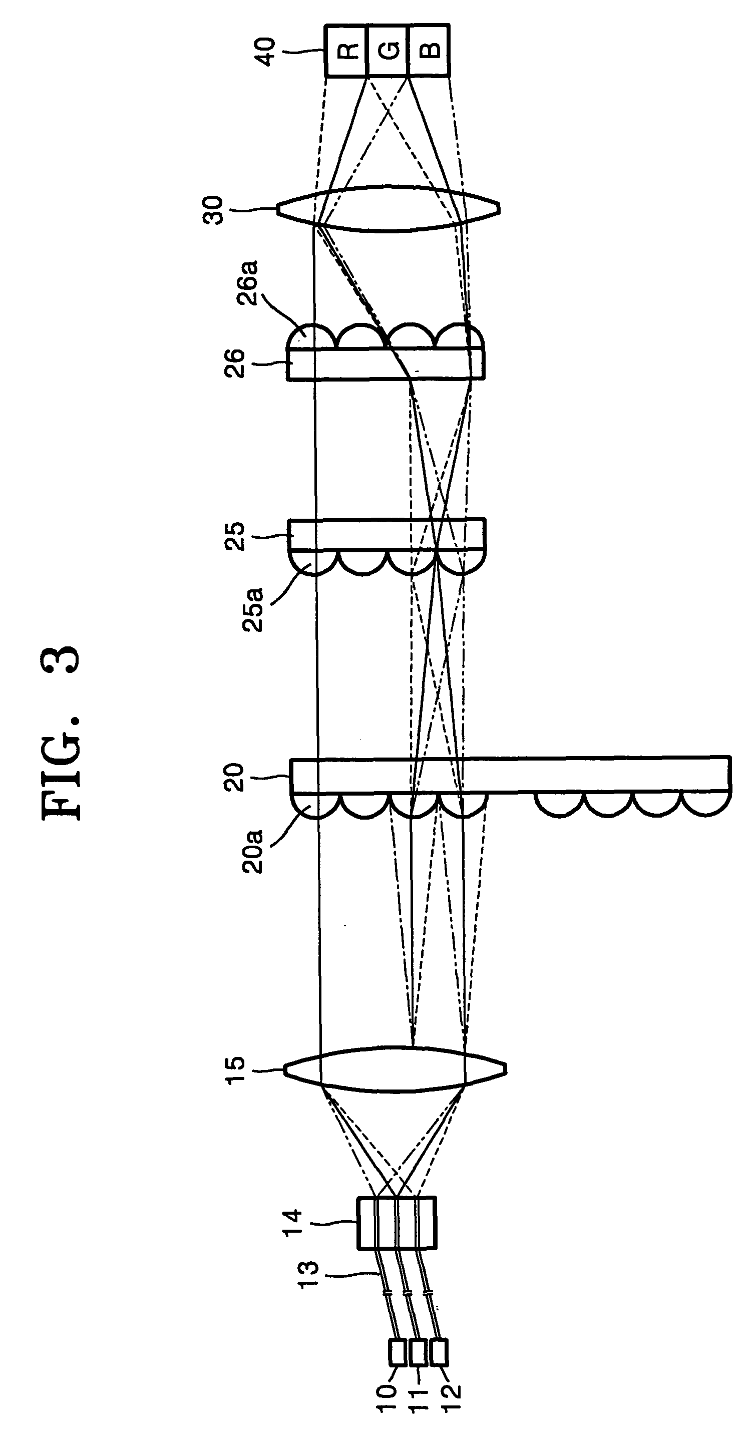
[0033]Referring to FIG. 3, a projection system according to an embodiment of the present invention includes first, second, and third light emitting units 10, 11, and 12, a scrolling unit 20, and a light valve 40. The first, second, and third light emitting units 10, 11, and 12 radiate or emit beams at different wavelengths. The scrolling unit 20 scrolls the beams radiated by the first, second, and third light emitting units 10, 11, and 12. The light valve 40 forms an image by turning on or off its pixels according to an image signal. First and second fly-eye lenses 25 and 26 and a relay lens 30 may also be disposed along the light path betwee...


PUM


Abstract

A projection system including light emitting units, a scrolling unit, and a light valve. The light emitting units emitting light beams of different wavelengths. The scrolling unit has spirally arranged cylinder lens cells which separate the light beams into color beams and scroll the color beams when the scrolling unit is rotated. The light valve receives, at different positions, the color beams transmitted by the scrolling unit and forms a color image by turning pixels on or off according to an input image signal.

Description

CROSS-REFERENCE TO RELATED APPLICATIONS[0001]This application claims the benefit of Korean Application No. 2002-50307, filed Aug. 24, 2002, in the Korean Intellectual Property Office, the disclosure of which is incorporated herein by reference.BACKGROUND OF THE INVENTION[0002]1. Field of the Invention[0003]The present invention relates to a projection system, and more particularly, to a projection system of the single panel type which is optically efficient and compact.[0004]2. Description of the Related Art[0005]Projection systems are classified into 3-panel projection systems and single-panel projection systems according to the number of light valves for controlling the on / off operation of light emitted from a high-output lamp on a pixel-by-pixel basis and forming a picture. Single-panel projection systems can have a smaller optical system than three-panel projection systems but provide an optical efficiency of ⅓ of that of three-panel projection systems because the red (R), green...

Claims


Application Information

Patent Timeline
IPC IPC(8): G03B21/00G02F1/1335H04N5/74H04N9/31
CPCH04N9/3197H04N9/3117H04N5/74
Inventor KIM, DAE-SIKCHO, KUN-HOKIM, SUNA-HALEE, HEE-JOONG
Owner SAMSUNG ELECTRONICS CO LTD
Why Eureka
Try Eureka