Integrated transformer with stack structure

a stack structure and integrated transformer technology, applied in the direction of transformer/inductance details, transformer/inductance coil/winding/connection, inductance, etc., can solve the problems of difficult control of electrical characteristics of balun transformer b>400/b>, only determining the location of the center tap b>25/b>, and achieving the effect of easy determination of the center tap location

Active Publication Date: 2007-01-16
WINBOND ELECTRONICS CORP
View PDF6 Cites 62 Cited by
  • Summary
  • Abstract
  • Description
  • Claims
  • Application Information

AI Technical Summary

Benefits of technology

[0014]Accordingly, the present invention is directed to an integrated transformer with a stack structure. With symmetric structure of the windings, locations of center taps can be easily determined.
[0016]The present invention is directed to an integrated transformer with a stack structure, capable of effectively reducing insertion loss and enhancing coupling capabilities.
[0019]Accordingly, the first conductive line of the primary side is symmetric to the second conductive line of the primary side through the first axis, and the third conductive line of the primary side is symmetric to the fourth conductive line of the primary side through the second axis. In addition, first conductive line of the secondary side and the second conductive line of the secondary side are symmetric to the first conductive line of the primary side and the second conductive line of the primary side through the third axis, respectively. The third conductive line of the secondary side and the fourth conductive line of the secondary side are symmetric to the third conductive line of the primary side and the fourth conductive line of the primary side through the fourth axis, respectively. Due to the symmetric pattern of the primary side and the secondary side, the locations of center taps can be easily determined.
[0020]Because portions of both first winding and the second winding are disposed over the surface of the bottom dielectric layer and the surface of the middle dielectric layer, the primary side and the secondary side of the present invention have the same parasitic capacitance. Electrical characteristics can thus be well controlled. Moreover, these windings have horizontal and vertical electromagnetic coupling, so insertion loss can be reduced and coupling capabilities are enhanced.

Problems solved by technology

The disadvantage of the BALUN transformer 200 is that the location of the center tap 25 can only be determined after electrical performance of winding is measured.
In these BALUN transformers disclosed in U.S. Pat. No. 3,904,911, the winding conductive line is only one circle and is not practical.
Therefore, electrical characteristics of the BALUN transformer 400 are hard to control.

Method used


Image

  • Integrated transformer with stack structure
  • Integrated transformer with stack structure
  • Integrated transformer with stack structure

Examples


first embodiment

[0037

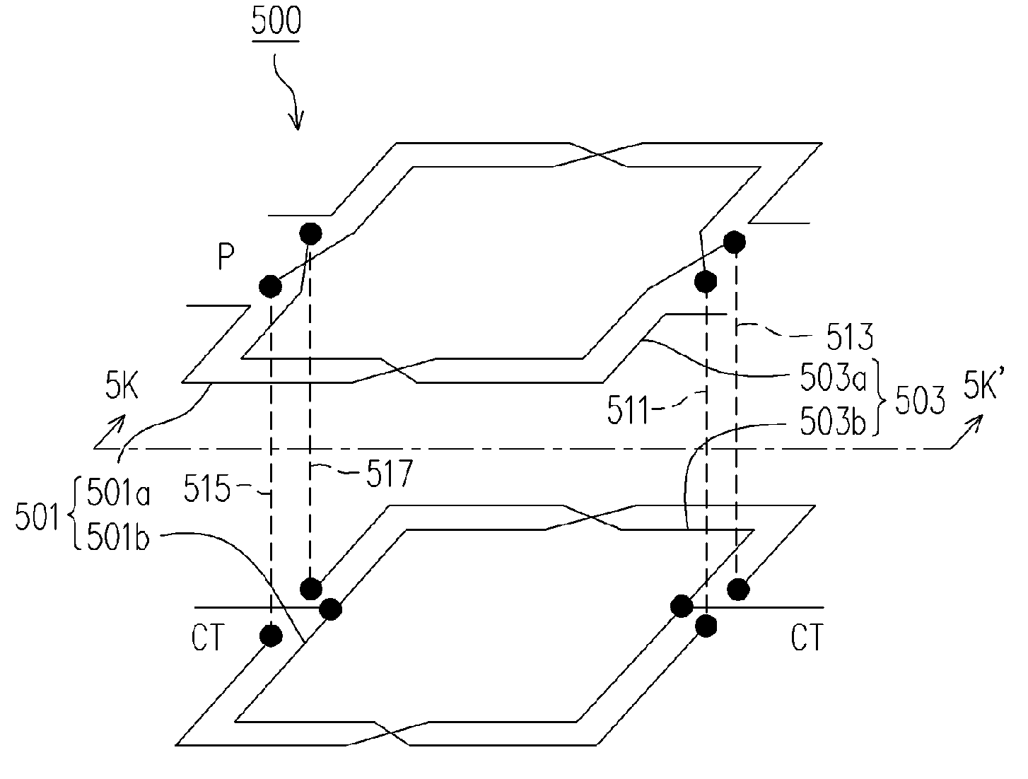
[0038]FIG. 5A is a schematic drawing showing a 3-D integrated transformer with a stack structure according to the first embodiment of the present invention. FIG. 5B is a cross sectional view of the integrated transformer with a stack structure along 5K–5K′ in FIG. 5A. Referring to FIGS. 5A and 5B, the integrated transformer 500 comprises a first winding 501 and a second winding 503. Wherein, portions of the first winding 501 and the second winding 503, 501a and 503a, respectively, are disposed over the surface of the middle dielectric layer 505b. The other portions 501b and 503b are over the surface of the bottom dielectric layer 505a. In addition, in order to form a symmetric pattern within and between these windings, the top portion 501a of the first winding 501 crosses over the top portion 503b of the second winding 503, and the same applies to the bottom portion 501b of the first winding 501 and the bottom portion 503b of the winding 503. These two windings lie reversed in ...

second embodiment

[0050

[0051]FIG. 6 is a top view of an integrated transformer with a stack structure according to the second embodiment of the present invention. Referring to FIG. 6, the portion 610 is equivalent to the surface portion of the middle dielectric layer 505b in FIG. 5B. The portion 620 is equivalent to the surface of the bottom dielectric layer 505a. The structure of the integrated transformer in the present embodiment can refer to the first embodiment and detailed descriptions are not repeated.

[0052]In FIG. 6, the numbers of coils on portions of 610 and 620 of the primary side P can be of even numbers, such as 2, 4, 6, . . . etc. Accordingly, the total number of the coils on the primary side P is 4, 8, 12, . . . etc. Similarly, the secondary side S has the same structure and detailed descriptions are not repeated.

third embodiment

[0053

[0054]FIG. 7 is a top view of an integrated transformer with a stack structure according to the third embodiment of the present invention. Referring to FIG. 7, the portion 710 is equivalent to the surface portion of the middle dielectric layer 505b in FIG. 5B. The portion 720 is equivalent to the surface of the bottom dielectric layer 505a. The structure of the integrated transformer can refer to the first embodiment and detailed descriptions are not repeated.

[0055]In FIG. 7, the numbers of coils on portions of 710 and 720 of the primary side P can be multiples by 1.5, such as 1.5, 3, 4.5, . . . etc. Accordingly, the total number of the coils on the primary side P is 3, 6, 9, . . . etc. Similarly, the secondary side has the same structure and detailed descriptions are not repeated.


PUM

PropertyMeasurementUnit
conductiveaaaaaaaaaa
impedanceaaaaaaaaaa
voltageaaaaaaaaaa

Abstract

An integrated transformer with a stack structure comprises a middle dielectric layer, a bottom dielectric layer, a first winding and a second winding. A portion of the first winding is disposed over a surface of the middle dielectric layer and the remaining portion of the first winding is disposed over a surface of the bottom dielectric layer. A portion of the second winding is disposed over the surface of the middle dielectric layer and the remaining portion of the second winding is disposed over the surface of the bottom dielectric layer. The second winding doesn't intersect with the first winding. The portions of the first and second windings over the surface of the middle dielectric layer connect with the remaining portions of the first and second windings over the surface of the bottom dielectric through via plugs.

Description

CROSS-REFERENCE TO RELATED APPLICATION[0001]This application claims the priority benefit of Taiwan application Ser. No. 93130516, filed Oct. 8, 2004.BACKGROUND OF THE INVENTION[0002]1. Field of the Invention[0003]The present invention relates to an integrated transformer, and more particularly to an integrated transformer with a stack structure.[0004]2. Description of the Related Art[0005]For integrated circuits applied in wireless communication, transformers convert impedance among different signals. In order to effectively reduce circuit interference resulting from common-mode noises, more and more circuits adopt the design of differential signal pairs. Accordingly, transformers must transform single-ended unbalance signals into differential balance signals. One of these transformers is the balance-to-unbalance (BALUN) transformer.[0006]FIG. 1 is a schematic drawing showing an equivalent circuit of a BALUN transformer. Referring to FIG. 1, the BALUN transformer 100 comprises a pri...

Claims


Application Information

Patent Timeline
Patent Type & Authority Patents(United States)
IPC IPC(8): H01F5/00H01L27/00
CPCH01F17/0006H01F2021/125H01F2017/0046H01F27/2804
Inventor HUANG, KAI-YI
Owner WINBOND ELECTRONICS CORP
Why Eureka
Try Eureka