Interrogator and goods management system adopting the same

a technology of interrogator and goods management system, applied in the field of interrogator, can solve the problems of deteriorating antenna characteristics, difficult to achieve the power that the transponder needs, and difficult to realize a uniform electromagnetic field over a wide range, so as to achieve the effect of increasing the electromagnetic energy supplied to the transponder and ensuring the electromagnetic energy over a wide area

Inactive Publication Date: 2007-01-16
HITACHI LTD
View PDF53 Cites 51 Cited by
  • Summary
  • Abstract
  • Description
  • Claims
  • Application Information

AI Technical Summary

Benefits of technology

[0012]Thus, in the sleeve antenna shown in FIG. 3, an intensified and uniform electromagnetic energy is securely attained to be concentrated on areas near the monopole antenna and the coaxial cable portion. Accordingly, multiple transponders can be arrayed in that area. In other words, even if the antenna characteristics of the transponders are deteriorated, or even if the electromagnetic distributions are different in the fluctuations, the areas adjacent to the antenna elements attain an intensified electromagnetic field, which makes it possible to secure the electromagnetic energy over a wide area that the

Problems solved by technology

However, in a quasi-microwave band, for example, a phase synthesis of an electromagnetic wave radiated from the interrogator and electromagnetic waves radiated from the transponders in the space is apt to create fluctuations of the electromagnetic waves; and it is difficult to realize a uniform electro

Method used


Image

  • Interrogator and goods management system adopting the same
  • Interrogator and goods management system adopting the same
  • Interrogator and goods management system adopting the same

Examples


first embodiment

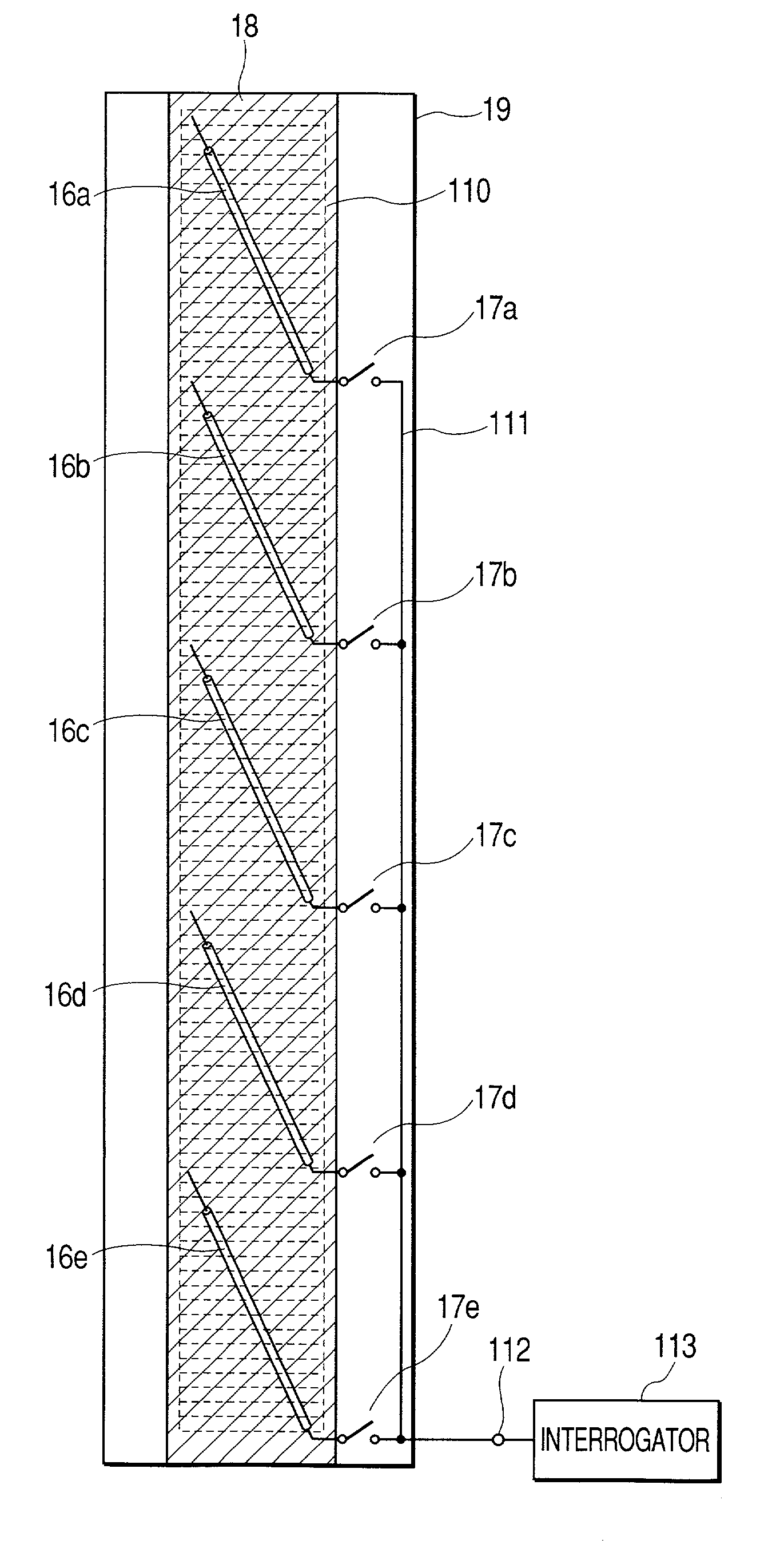
[0037]FIGS. 5(a) and 5(b) illustrate an interrogator as the invention, which includes plural sleeve antennas switched by selectors and plural transponders arrayed near each of the sleeve antennas, and manages multiple transponders as a whole. FIG. 5(a) is the plan view and FIG. 5(b) is the side view. In FIGS. 5(a) and 5(b), 16a–16e denote the sleeve antennas as shown in FIG. 3, 113 denotes an interrogator body, 111 an RF signal line that supplies the sleeve antennas 16a–16e with an RF signal from the interrogator body 113 through an input / output terminal 112, and 17a–17e denote RF signal selectors that switch the connections between each of the sleeve antennas and the RF signal line 111. Each of the sleeve antennas has the outer conductor grounded at the feed point. Further, 19 denotes a dielectric plate, and 18 a conductive plate (ground plane) stuck on the rear side of the dielectric plate 19. The above construction forms an interrogator antenna incorporated with the interrogator ...

second embodiment

[0047]The sleeve antennas 26a–26e in the second embodiment have the plane of vibration perpendicular to the plane of vibration of the rectangular transponder antennas. This configuration of the plane of vibration of the transponders being perpendicular to that of the sleeve antennas weakens the impedance coupling between the sleeve antennas and the transponder antennas, and decreases the power to be supplied. However, in reverse, the load is apt to be lessened each other, and thereby the optimization of the distance between them will realize an interrogator with the sleeve antennas capable of communicating multiple transponders.

third embodiment

[0048]FIGS. 7(a) and 7(b) illustrate an interrogator as the invention, in which the sleeve antennas are disposed to shorten the RF signal line for the power distribution. FIG. 7(a) and FIG. 7(b) are the plan view and the side view, respectively. To shorten the RF signal line is to decrease the loss of the RF signal generated.

[0049]In FIGS. 7(a) and 7(b), 36a–36e denote the sleeve antennas disposed with the orientations reversed each other, in parallel to the longitudinal direction of a dielectric plate 39. 311 denotes an RF signal line that feeds the RF signal to the antennas arranged in that manner, 312 an RF signal input / output terminal arranged virtually on the center of the RF signal line 311. The other configuration is the same as in the second embodiment. That is, the sleeve antennas 36a–36e, RF signal selectors 37a–37e, RF signal line 311, RF signal input / output terminal 312, and ground plane 38 configure an interrogator antenna, and a transponder group 310 is disposed very c...


PUM


Abstract

An interrogator with an antenna that allows information exchanges with multiple transponders in a shorter distance of communication, by securing an intensified and uniform electromagnetic energy concentrated on areas near antenna elements. The interrogator is furnished with a sleeve antenna that includes a monopole conductor of ¼ wavelength (free space wavelength) continuously connected to a core wire of a coaxial cable on one end thereof, and a feed point on the other end, in which the sleeve antenna is grounded at the feed point. The interrogator has a plurality of the transponders arrayed near the antenna, and a plurality of the antennas selected by RF signal selectors. The interrogator antenna allows movable body identification such as in a goods management system for identifying multiply arrayed goods.

Description

BACKGROUND OF THE INVENTION[0001]The present invention relates to an interrogator that exchanges information with transponders by using an RF signal of the microwave band, specifically to an interrogator provided with antennas suitable for exchanging RF signals with multiple transponders.[0002]Movable body identification equipment (identification system by radio waves) is composed of an interrogator and plural transponders responding to the interrogator. The interrogator radiates an RF signal of the microwave band (including the quasi-microwave band) from an antenna to the transponders not having the cells, and exchanges information with the transponders. The transponders receive the RF signal from the interrogator with small antennas, and rectify the RF signal to attain the DC power supply, clocks and data, and in response to the data, answer the information of the memory to the interrogator from the small antennas.[0003]The exchange of information includes, for example, discrimina...

Claims


Application Information

Patent Timeline
IPC IPC(8): G01S13/74G01S13/00H01Q9/04G06K19/07G06K7/08G06K7/10G06K17/00H01Q1/22H01Q3/24H01Q9/30H01Q21/06
CPCG06K7/10336G06K7/10346H01Q1/22H01Q21/061H01Q3/24H01Q9/30H01Q1/2216
Inventor SAITO, TAKESHI
Owner HITACHI LTD
Why Eureka
Try Eureka