Optical disk reproducing apparatus and method for controlling spindle motor

a technology of optical disk and reproducing apparatus, which is applied in the direction of digital signal error detection/correction, instruments, recording signal processing, etc., can solve the problems of corresponding inability to miniaturize the apparatus, and increase in apparatus production cos

Inactive Publication Date: 2007-01-16
FUNAI ELECTRIC CO LTD
View PDF6 Cites 0 Cited by
  • Summary
  • Abstract
  • Description
  • Claims
  • Application Information

AI Technical Summary

Benefits of technology

[0010]It is therefore an object of the invention is to provide an optical disk reproducing apparatus in which the time of supplying a brake signal can be calculated without using an FG sensor, whereby rotation of an optical disk can be stopped.

Problems solved by technology

The production cost of the apparatus is correspondingly increased, and miniaturization of the apparatus is inhibited.
In the same manner as the conventional optical disk reproducing apparatus, therefore, the production cost of an apparatus is increased by a degree corresponding to the FG sensor, and miniaturization of the apparatus is inhibited.

Method used


Image

  • Optical disk reproducing apparatus and method for controlling spindle motor
  • Optical disk reproducing apparatus and method for controlling spindle motor
  • Optical disk reproducing apparatus and method for controlling spindle motor

Examples


Embodiment Construction

[0020]Referring now to the accompanying drawings, a description will be given in detail of a preferred embodiment of the invention.

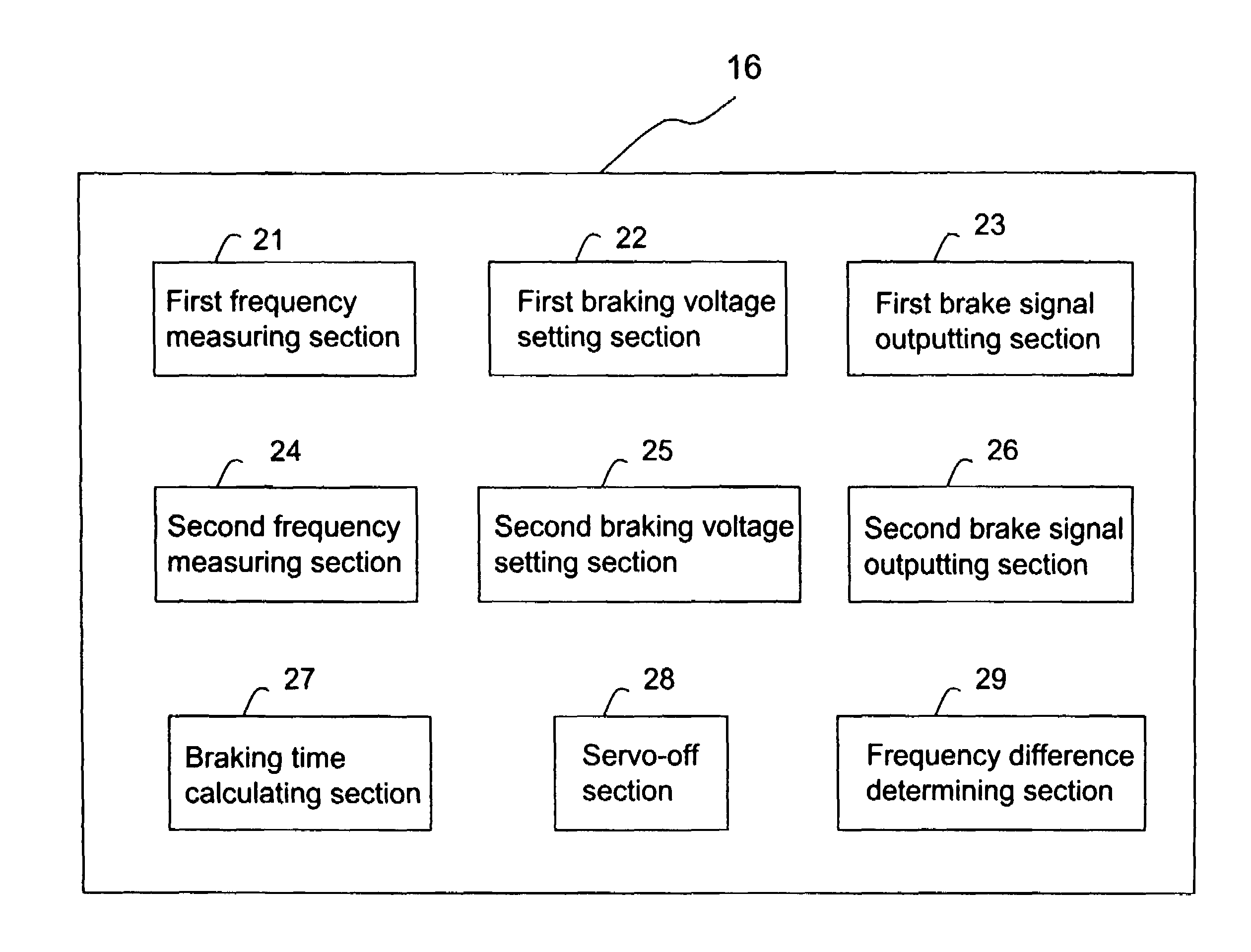
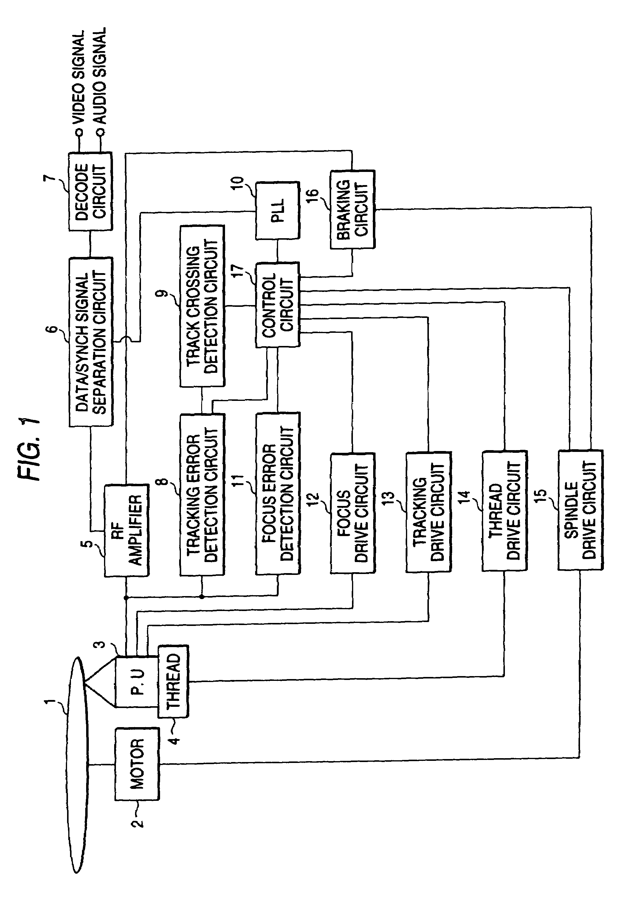
[0021]FIG. 1 is a block diagram showing the configuration of an optical disk reproducing apparatus according to an embodiment of the invention. The optical disk reproducing apparatus includes: an optical pickup 3 which emits a laser beam for reproducing information recorded on an optical disk 1 serving as a recording medium, and which receives light reflected from the optical disk 1; a spindle motor 2 which rotates the optical disk 1; a spindle motor driving circuit 15 which drives the spindle motor 2; a tracking drive circuit 13 which drives an actuator (not shown) for performing a tracking servo control on the optical pickup 3; a focus drive circuit 12 which drives an actuator (not shown) for performing a focus servo control on the optical pickup 3; a sled mechanism 4 which moves the optical pickup 3 in a radial direction of the optical disk 1; and a s...


PUM

PropertyMeasurementUnit
frequencyaaaaaaaaaa
frequency difference determiningaaaaaaaaaa
braking timeaaaaaaaaaa

Abstract

In a process of braking an spindle motor, a frequency of a read clock signal synchronized with an RF signal output from an RF amplifier is measured as a first frequency by a braking control circuit. A brake is then applied to the spindle motor for a predetermined time. Thereafter, the frequency of the read clock signal is measured as a second frequency. Next, the braking time is calculated on the basis of: a frequency difference obtained by subtracting the second frequency from the first frequency; the first frequency; and a measuring time from the timing when the first frequency is measured to the timing when the second frequency is measured.

Description

BACKGROUND OF THE INVENTION[0001]1. Field of the Invention[0002]The present invention relates to an optical disk reproducing apparatus which reproduces information recorded on an optical disk, and more particularly to an optical disk reproducing apparatus which has a function of calculating a time of supplying a brake signal to a spindle motor for rotating an optical disk. The present invention also relates to a method for controlling a spindle motor in which rotates an optical disk.[0003]2. Description of the Related Art[0004]In a conventional optical disk reproducing apparatus, a spindle motor for rotating an optical disk is controlled in the following manner. A voltage corresponding to a phase difference between a synchronization signal contained in a reproduction signal which is output from an optical pickup in a process of reproducing an optical disk, and a predetermined reference signal is produced with using a PLL (Phase-Locked Loop). The voltage is used as a motor control si...

Claims


Application Information

Patent Timeline
Patent Type & Authority Patents(United States)
IPC IPC(8): G11B7/00G11B19/22G11B19/28
CPCG11B19/28
Inventor YAMAGUCHI, TAKAHIRO
Owner FUNAI ELECTRIC CO LTD
Why Eureka
Try Eureka