Radio frequency identification for transfer of component information in fiber optic testing

a technology of fiber optic testing and component information, applied in the direction of instruments, optical elements, and reradiation, can solve the problems of loss of power of optical signals, attenuation losses, and loss of insertion power of optical data signals at the interface, and achieve the effect of facilitating data transmission

Inactive Publication Date: 2007-01-23
STRATOS INT
View PDF24 Cites 162 Cited by
  • Summary
  • Abstract
  • Description
  • Claims
  • Application Information

AI Technical Summary

Benefits of technology

[0010]It is an object of the invention to provide a device which facilitates the transmission of data from an optical test unit to a connector via radio frequency identification components, where the data concerns performance characteristics of the connector and associated cable.
[0011]It is another object of the invention to provide a device which facilitates the transmission of data from a connector to a host device via radio frequency identification components.

Problems solved by technology

Loss of power of the optical signal can occur due to attenuation and insertion loss.
The attenuation losses are typically due to the less than perfect optical transparency material used to make the optical fiber and due to the angle and surface preparation of the terminal ends of the optical fiber.
An insertion loss is the power loss of the optical data signal at the interface between one end of the fiber optic cable and the device to which it is connected.

Method used


Image

  • Radio frequency identification for transfer of component information in fiber optic testing
  • Radio frequency identification for transfer of component information in fiber optic testing
  • Radio frequency identification for transfer of component information in fiber optic testing

Examples


Embodiment Construction

[0033]Referring now to the drawings, wherein like reference numerals designate identical or corresponding parts throughout the several views, and more particularly to FIGS. 16, and 17 thereof, embodiments of the present invention are displayed therein. However, FIGS. 6–15 are first discussed so as to present features of the present invention that are not shown in FIGS. 16, and 17 due to reasons of clarity.

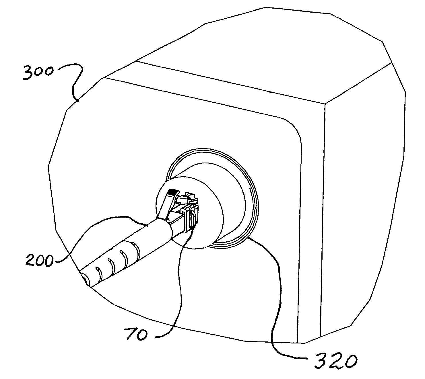
[0034]FIG. 6 is a perspective view of a fiber optic cable 30 having a fiber optic connector 10. The fiber optic connector 10 includes a release lever 40. Attached to the fiber optic connector 10 is a strain relief boot 20. Also attached to, or mounted on or in, the fiber optic connector 10 is a transponder 70. The transponder 70 can be affixed to the fiber optic connector 10 with an adhesive material or a clip (not shown). The clip physically squeezes or clamps the transponder 70 to the fiber optic connector 10. Alternatively, the transponder 70 can be insert molded into the body o...


PUM

PropertyMeasurementUnit
optical testaaaaaaaaaa
optical propertyaaaaaaaaaa
optical performanceaaaaaaaaaa

Abstract

The device includes a connector, a transponder, an optical test unit, an antenna, and a transceiver. The transponder is attached to the connector. The antenna is attached to the optical test unit. The transceiver is electrically connected to the antenna. When the connector is attached to the optical test unit and the optical test unit performs diagnostic testing on the connector and its associated optical fiber, the results or data of the diagnostic testing are stored in the optical test unit for later downloading from the optical test unit to the transponder. The test data can include attenuation loss, insertion loss, and back reflection test data. Once the connector is connected to a host device, the data associated with the specific connector can uploaded from the transponder to the host device.

Description

[0001]This application is a continuation-in-part of U.S. Ser. No. 10 / 816,749, filed Apr. 2, 2004. The aforementioned parent application is hereby incorporated herein by reference.BACKGROUND OF THE INVENTION[0002]1. Field of the Invention[0003]The present invention pertains to radio frequency identification devices. The invention more particularly concerns the application of radio frequency identification technology for the transfer of component information in fiber optic testing.[0004]2. Discussion of the Background[0005]Radio frequency identification devices (RFID) are known in the art. Typically, radio frequency identification systems incorporate an antenna or coil, a transceiver (with decoder), and a transponder (RF tag). Often times the antenna and the transceiver are packaged together so as to form a reader or interrogator. The transponder includes a transponder antenna and an integrated circuit chip attached to the transponder antenna. The antenna or coil emits a radio wave wh...

Claims


Application Information

Patent Timeline
Patent Type & Authority Patents(United States)
IPC IPC(8): G06K19/06G01N21/00G02B6/36G01S13/08G02B6/38G08B21/00H04B7/00H04B10/00H04B10/12H04Q5/22
CPCG02B6/3807G02B6/381G02B6/385H04B10/25758G02B6/3895G02B6/3897G02B6/3851
Inventor DURRANT, RICHARD C. E.KROWIAK, MARK
Owner STRATOS INT
Why Eureka
Try Eureka