Injection molding machine

a molding machine and injection molding technology, applied in the direction of metal-working machine components, manufacturing tools, food shaping, etc., can solve the problems of damage to the encoder, insufficient rigidity of the conventional molding machine, and insufficient rigidity to resist a load in the vertical or lateral direction,

Inactive Publication Date: 2007-01-23
TOSHIBA MASCH CO LTD
View PDF20 Cites 8 Cited by
  • Summary
  • Abstract
  • Description
  • Claims
  • Application Information

AI Technical Summary

Benefits of technology

[0011]It has now been formed by the present inventors that this object can be achieved by not using an intermediate plate nor a tie bar in an injection mechanism, fixing a charging motor and a mechanism for transmitting the rotation of the motor to a screw both to a body frame so that they may not move in the axial direction, and providing a linear guide for guiding the movement of the screw in the axial direction.

Problems solved by technology

This entails the problem that a high acceleration upon a high-speed injection can damage the encoder.
The conventional molding machine, however, has an insufficient rigidity to resist a load in the vertical direction or in the lateral direction (width direction of the machine) which may be caused by, for example, a misalignment from the injection shaft.
The use of thicker tie bars, however, necessitates an extra space for assembly, requires a larger-sized associated parts and incurs an increased cost.

Method used


Image

  • Injection molding machine
  • Injection molding machine
  • Injection molding machine

Examples


Embodiment Construction

[0018]A preferred embodiment of the present invention will now be described in detail with reference to FIGS. 1 through 4.

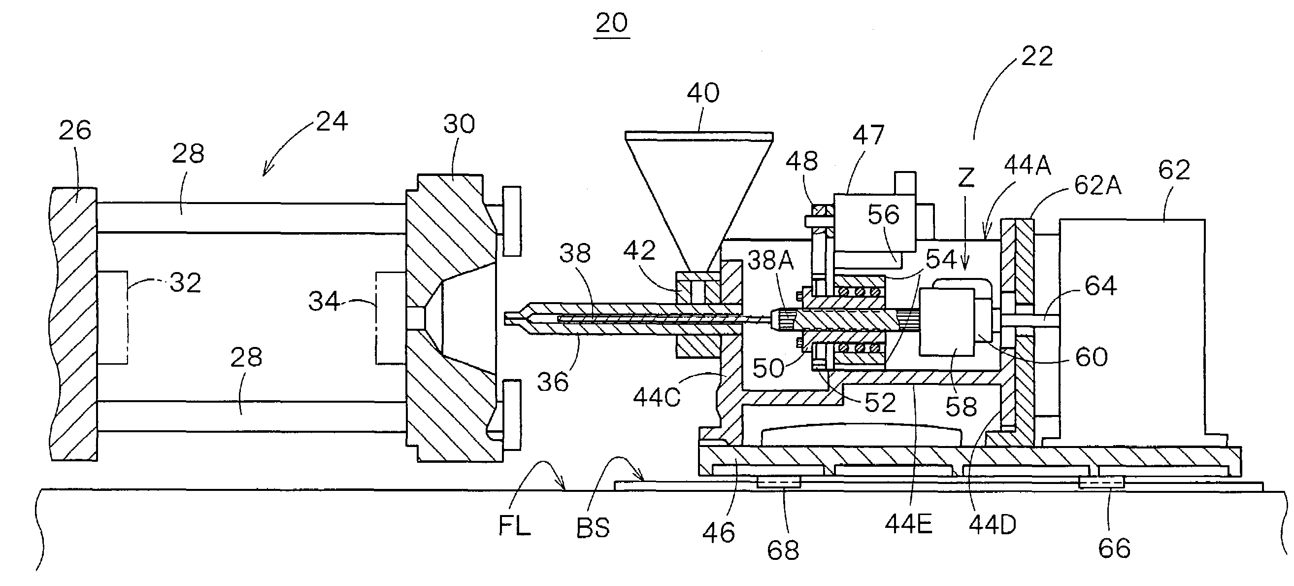
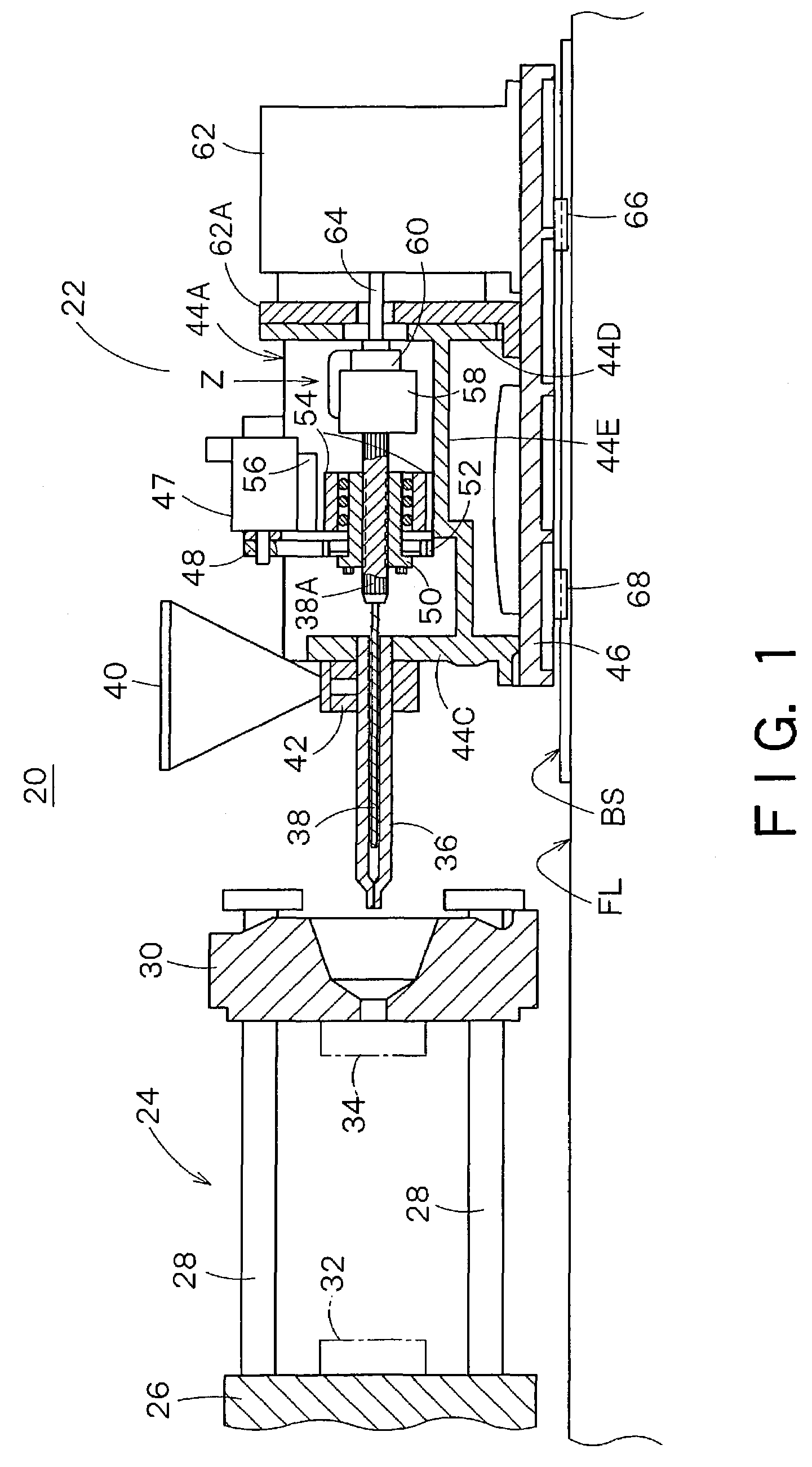
[0019]FIG. 1 shows a front view of an injection molding machine according to the present invention, as viewed from the operation side. In FIG. 1, reference numeral 20 denotes the injection molding machine, which is comprised of an injection unit 22 and a mold clamping unit 24 that is shown schematically. The mold clamping unit 24 includes a movable die plate 26 to which a movable mold 32 is mounted and a fixed die plate 30 to which a fixed mold 34 is mounted, which are opposed to each other and coupled by tie bars 28.

[0020]The injection unit 22 is installed on a base BS, which is fixed on a concrete floor FL, via linear sliders 66, 68 that are mounted to the lower surface of a bottom plate 46. The linear sliders 66, 68 are slidably disposed on the base BS, and can move the bottom plate 46 right and left via a not-shown nozzle touch driving mechanism. Further, the...


PUM

PropertyMeasurementUnit
forceaaaaaaaaaa
heightaaaaaaaaaa
torqueaaaaaaaaaa

Abstract

There is provided an injection molding machine provided with an injection mechanism that enables a high-speed injection.The injection molding machine includes: a heating barrel for melting and kneading a resin fed from a hopper, said barrel having an injection nozzle at its front end; a screw movably and rotatably inserted in the heating barrel; a screw drive shaft coupled at its one end to the rear end of the screw; charging means including a charging motor for rotationally driving the screw drive shaft to rotate the screw so as to melt the resin in the heating barrel while conveying the resin forward of the screw, and measure the volume of the molten resin, and torque transmission means for transmitting the driving torque of the charging motor to the screw drive shaft and permitting a displacement of the screw drive shaft in the axial direction; a body frame fixing and supporting the charging motor and the torque transmission means, said frame including a front plate fixing and supporting the base of the heating barrel; injection drive means including a linear-movement shaft coupled to the rear end of the screw drive shaft and movable in the axial direction, and an injection motor for advancing the screw and producing an injection force for injecting the molten resin in the heating barrel; and shaft coupling means for coupling the rear end of the screw drive shaft to the linear-movement shaft such that only a thrust in the axial direction is transmitted to the screw drive shaft.

Description

CROSS REFERENCE TO RELATED APPLICATIONS[0001]This application claims priority to Japanese application No. 2002-159647, filed May 31, 2002, the contents of which is incorporated herein in its entirety by reference.BACKGROUND OF THE INVENTION[0002]1. Field of the Invention[0003]The present invention relates to an injection molding machine, and more particularly to an injection unit which enables a high-speed injection.[0004]2. Background Art[0005]FIG. 5 shows a conventional motor-driven injection molding machine. The injection molding machine 1 includes a front plate 3 and a rear plate 4 on a fixed base 2, which plates 3, 4 are coupled to each other by tie bars 5. A barrel 6 is fixed at the base portion to the front plate 3. A screw 7 is housed in the barrel 6. The screw 7 can be driven to rotate by means of a charging motor 8.[0006]The base portion of the screw 7 is rotatably supported, via a bearing 9, by an intermediate plate 10. The intermediate plate 10 and the charging motor 8 c...

Claims


Application Information

Patent Timeline
Patent Type & Authority Patents(United States)
IPC IPC(8): B29B11/06B29C45/17B29C45/50B29C45/77
CPCB29C45/5008Y10T408/75B29C2045/5032B29C2045/1793
Inventor ONUMA, HIROYUKIOGURA, KATSUHITOKIDO, KATSUYOSHITOKUYAMA, HARUMICHI
Owner TOSHIBA MASCH CO LTD
Why Eureka
Try Eureka