Apparatus and method for separating and filtering particles and organisms from flowing liquids

a technology of filtering apparatus and flowing liquid, applied in the direction of separation process, multi-stage water/sewage treatment, nature of treatment water, etc., can solve the problem of increasing ballasting time required, and achieve the effect of simplifying operation problems, reducing the size and weight of the devi

Inactive Publication Date: 2007-01-23
NILSEN HALVOR +1
View PDF1 Cites 41 Cited by
  • Summary
  • Abstract
  • Description
  • Claims
  • Application Information

AI Technical Summary

Benefits of technology

[0005]It is an objective of the invention to provide a device that can separate and filter particles and organisms from a high volume flow of liquid under low operating pressure thereby reducing the size, weight of the device and thereby simplifying operational issues relating to the challenge of treating ballast water aboard ships.
[0007]This invention provides for, both the ease of use of a hydro-cyclone and the efficiency of a filter, in one device.
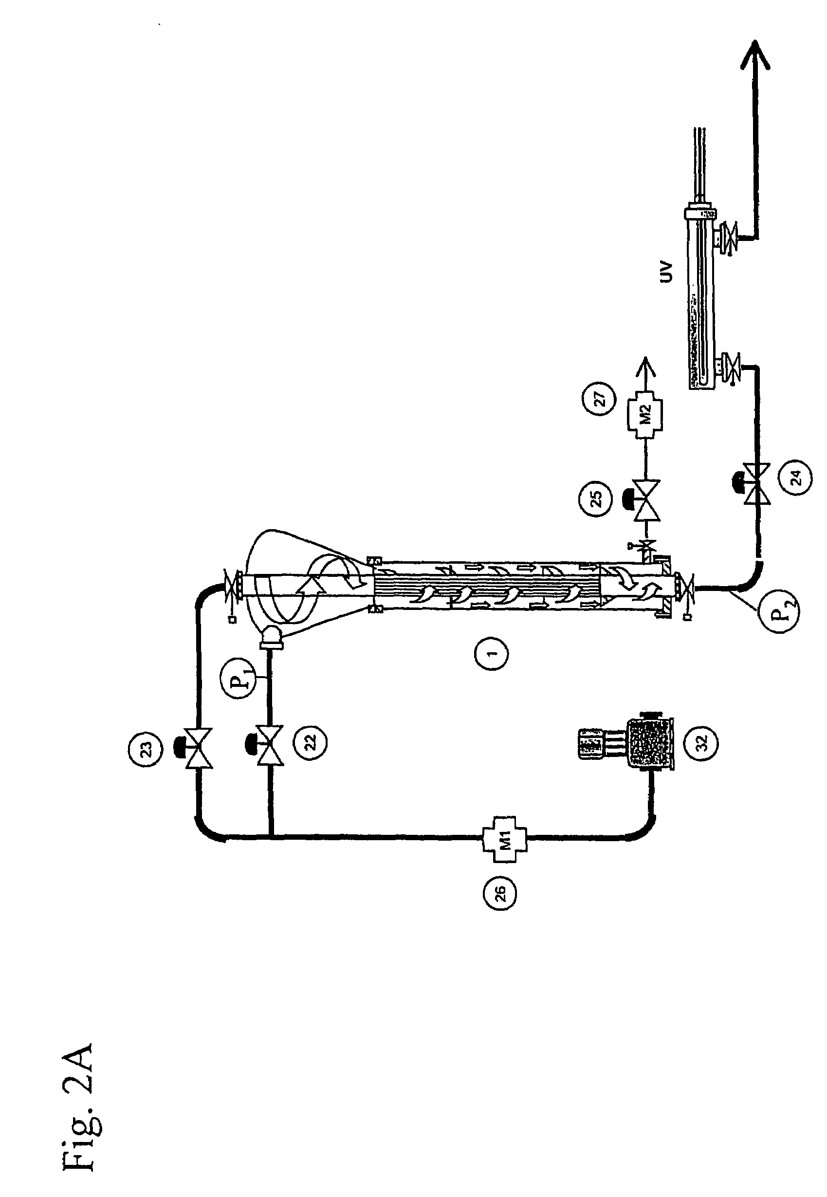
[0016]The filter / separating device of this invention is particularly suitable for the use of removing particles and organisms aboard ship ballast water systems, to reduce sediment loads in the ballast tanks and to prevent the spreading of aquatic nuisance species. Ships use high flow low-pressure pumps, and the pump room is normally below sea level creating a backpressure in the sludge discharge system.

Problems solved by technology

Traditional filters require large space to be able to treat the necessary flow volume requirements, and, in addition, increase ballasting time required because of excessive back flushing cycles.

Method used


Image

  • Apparatus and method for separating and filtering particles and organisms from flowing liquids
  • Apparatus and method for separating and filtering particles and organisms from flowing liquids
  • Apparatus and method for separating and filtering particles and organisms from flowing liquids

Examples


Embodiment Construction

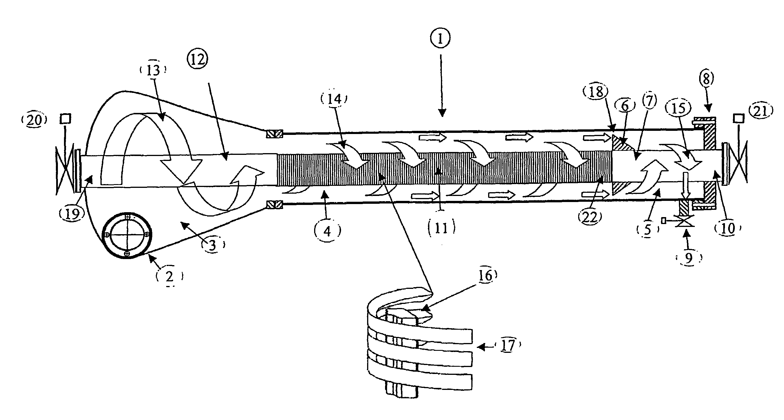
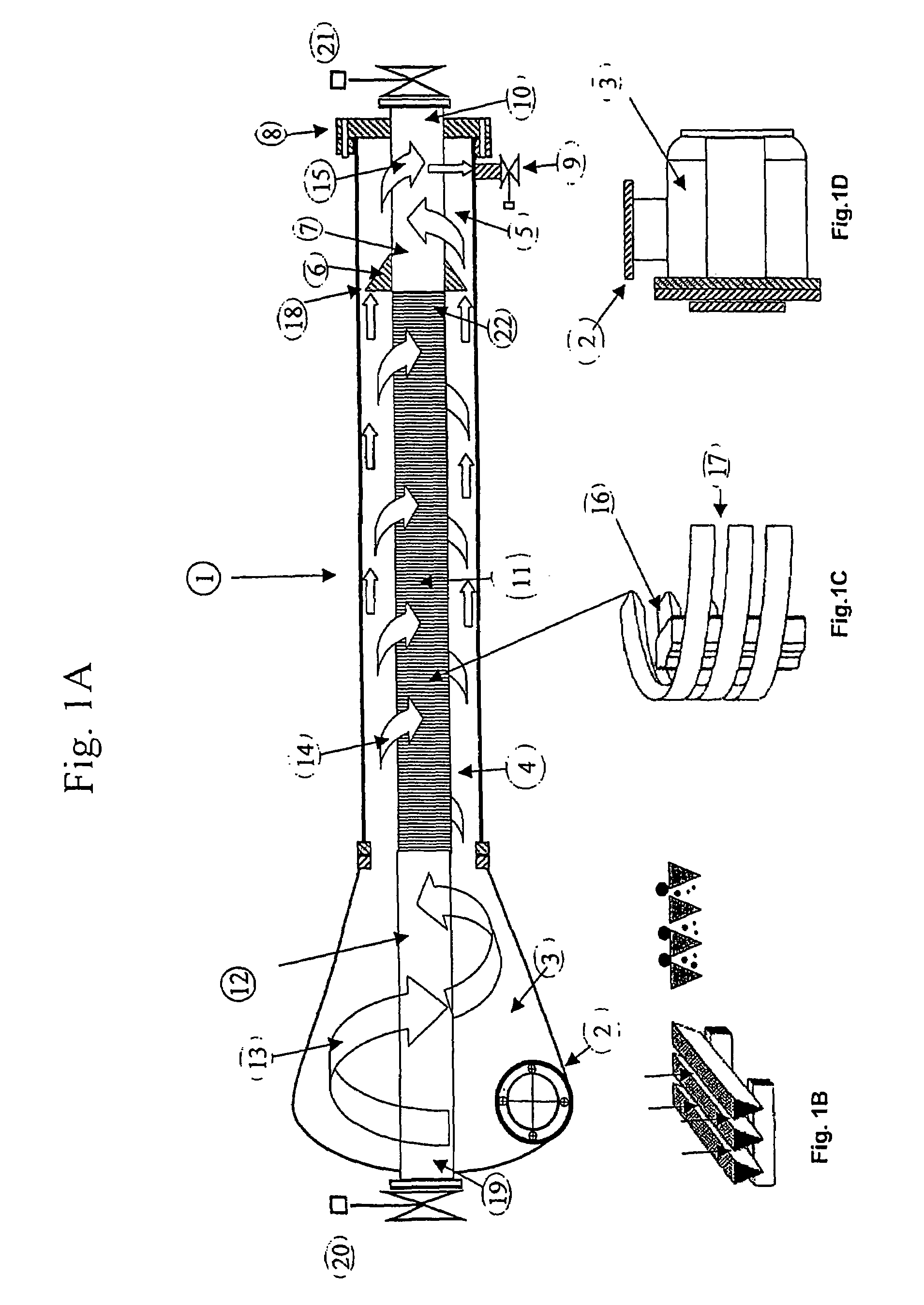
[0027]Referring to FIG. 1A of the drawing, the principal components of the liquid separator and filter device (1) are inlet chamber (3), separation and filter chamber (4), sludge chamber (5), and longitudinally disposed upper outlet pipe (19), cylindrical filter element (11) and lower outlet pipe (10).

[0028]FIG. 1A shows the filter and separator device (1), where the high volume, lower pressure liquid inlet (2) is mounted tangentially to circular inlet chamber (3) which is, in turn, connected to the separation and filter chamber (4). The inlet chamber is designed to meet the least possible fluid flow resistance and directs pumped liquid (13) in a helical circular motion around the longitudinal upper outlet pipe (19) which passes through the center of the inlet chamber (3). The liquid (13) forms a circular spinning flow into and through the separation and filter chamber (14) without forming a vortex as in traditional hydro-cyclones. The liquid (13) accelerates in the inlet chamber (3...


PUM

PropertyMeasurementUnit
wave lengthaaaaaaaaaa
pressureaaaaaaaaaa
angleaaaaaaaaaa

Abstract

A device (1) for separating and filtering particles and organisms from a high volume flowing liquid operating under low pressure. The device (1) includes a conical or cylindrical shape inlet chamber (3) were liquids enter tangentially creating a circular flow without creating a vortex, the liquids accelerate into a separation and filter chamber (14) where the liquids spin around a longitudinally disposed filter element (11) in the center of the chamber (14), with the centrifugal forces separating out larger and heavier particles towards the perimeter of the separation and filter chamber (14), and where smaller particles having a specific gravity closer to that of the liquid are filtered when the liquid penetrates through the filter element wall into the center of the filter element and flows out one of the longitudinal outlets of the unit. Ultraviolet light irreparably damages bacteria, microorganisms and pathogens contained in processed ballast water and may be incorporated as part of the system.

Description

FIELD OF THE INVENTION[0001]This application is directed to an apparatus and method for separating and filtering particles and organisms from a high volume flowing liquid operating under low pressure, with an automatic back flushing self-cleaning system, with ultraviolet treatment of water and use of the device in a ballast water treatment system for ships.BACKGROUND OF THE INVENTION[0002]The invention relates to a unit for separating and filtering particles and organisms from a high flowing liquid operating under low pressure with an automatic back flushing self-cleaning system aboard ships ballast water systems.DESCRIPTION OF PRIOR ART[0003]A separator is normally used to remove suspended solids particles from liquids having a different size and specific gravity. This is achieved by the liquid entering tangentially, setting up a circular flow creating a vortex then entering the separation chamber were the centrifugal action directs particles heavier than the liquid to the perimete...

Claims


Application Information

Patent Timeline
Patent Type & Authority Patents(United States)
IPC IPC(8): B01D35/06C02F1/00B01D21/00B01D29/33C02F1/32C02F1/38C02F9/00
CPCB01D21/0012B01D29/336C02F1/32C02F1/38B01D21/2411B01D21/267B01D21/34B01D21/26B01D29/48B01D29/606B01D29/66B01D29/908B01D2221/08C02F9/00C02F2103/008C02F2209/005C02F2303/16C02F1/001
Inventor NILSEN, HALVORNILSEN, BIRGIR
Owner NILSEN HALVOR
Why Eureka
Try Eureka