Electroactive polymer rotary clutch motors

a technology of rotary clutch motors and polymer rotary clutches, applied in the field of motors, can solve the problems of affecting and requiring a decrease in the speed of the increase torque, so as to achieve the effect of improving the torsional stiffness of the devi

Active Publication Date: 2007-01-23
SRI INTERNATIONAL
View PDF13 Cites 129 Cited by
  • Summary
  • Abstract
  • Description
  • Claims
  • Application Information

AI Technical Summary

Benefits of technology

[0014]In another aspect, the present invention relates to a mechanical-electrical power conversion system. The system comprises a power shaft configured to rotate about an axis. The system also has a transducer comprising an active area, which includes at least a portion of an electroactive polymer and at least two active area electrodes coupled to the portion of the electroactive polymer. The electroactive polymer includes pre-strain. The system further comprises a clutch for transmitting mechanical energy between the transducer and the power shaft, the clutch operably coupled to the power shaft and the transducer in a manner allowing engagement and disengagement of the power shaft to the transducer.
[0017]In another aspect, the present invention relates to a mechanical-electrical power conversion system. The system comprises a power shaft configured to rotate about an axis. The system also comprises a transducer comprising a first active area and a second active area. The first active area has at least two first active area electrodes and a first portion of the electroactive polymer arranged in a manner which causes the first portion to deflect in response to a change in electric field provided by the at least two first active area electrodes. The second active area has at least two second active area electrodes and a second portion of the electroactive polymer arranged in a manner which causes the second portion to deflect in response to a change in electric field provided by the at least two second active area electrodes. The system additionally comprises a clutch for transmitting mechanical energy between the transducer and the power shaft, the clutch operably coupled to the power shaft and the transducer in a manner allowing engagement and disengagement of the power shaft to the transducer.
[0018]In yet another aspect, the present invention relates to a device for converting between electrical energy and mechanical energy. The device comprises at least one transducer. Each transducer has at least two electrodes. Each transducer also comprises a polymer arranged in a manner which causes a first portion of the polymer to deflect in the first direction in response to a change in electric field and / or arranged in a manner which causes a change in electric field in response to deflection of the polymer in the first direction. The device further comprises a first substantially rigid member attached to a second portion of the polymer. The device additionally comprises a second substantially rigid member attached to a third portion of the polymer, the second portion and the third portion arranged to increase in distance therebetween upon deflection of the first portion. The device also comprises a first flexure coupled to the first and second members, wherein the first flexure improves torsional stiffness for the device.

Problems solved by technology

Since the power available for a DC motor is typically limited, an increase in torque requires a decrease in velocity and vice versa.
These motors are typically expensive and run from an AC source since the controller converts from AC to DC.
Though they can be stalled against a load, they will not tolerate a full voltage, zero velocity stall for an extended period of time without overheating.
However, these devices are very expensive and are commonly used in applications that justify their cost such as moving the flight control services of aircraft.
While being relatively good at holding the output in one position for indefinite period, they often are poor with motion and get out of phase with a desired control.
In addition, these motors are moderately expensive, have a low torque capacity, and also require special controllers.
But even stepper motors cannot provide a constant static torque at an arbitrary rotor position unless power is used.
This is why at stall and low speed conditions the efficiency of almost all electromagnetic motors is poor.
Air and hydraulic motors have more limited application than electric motors since they require the availability of a compressed air or hydraulic source.
Both these classes of motors provide poor energy efficiency due to the losses associated with the conversion of energy first from chemical or electrical energy to fluid pressure and then to mechanical output.
Although individual air motors and air cylinders are relatively cheap, these pneumatic systems are quite expensive when the cost of all the ancillary equipment is considered.
In addition to the specific drawbacks discussed with respect to each class of motor, all of the above motors classes are generally heavy, bulky and not suitable for many applications such as those requiring light weight continuous output.

Method used


Image

  • Electroactive polymer rotary clutch motors
  • Electroactive polymer rotary clutch motors
  • Electroactive polymer rotary clutch motors

Examples


Embodiment Construction

[0035]The present invention will now be described in detail with reference to a few preferred embodiments thereof as illustrated in the accompanying drawings. In the following description, numerous specific details are set forth in order to provide a thorough understanding of the present invention. It will be apparent, however, to one skilled in the art, that the present invention may be practiced without some or all of these specific details. In other instances, well known process steps and / or structures have not been described in detail in order to not unnecessarily obscure the present invention.

[0036]1. Overview

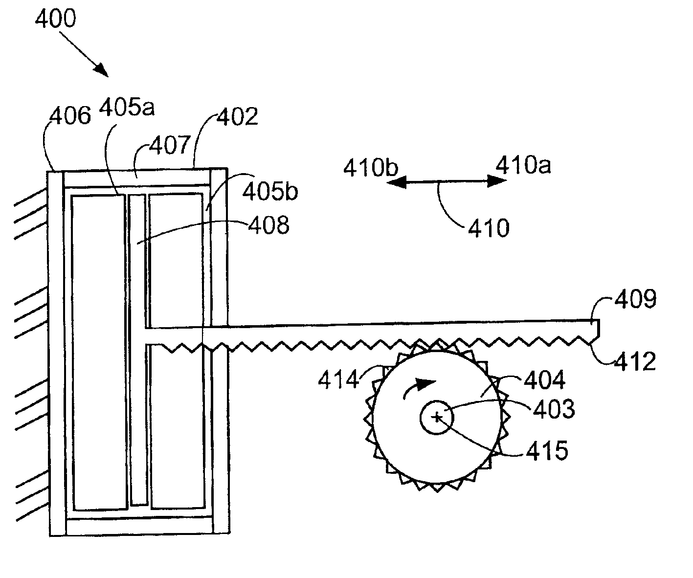
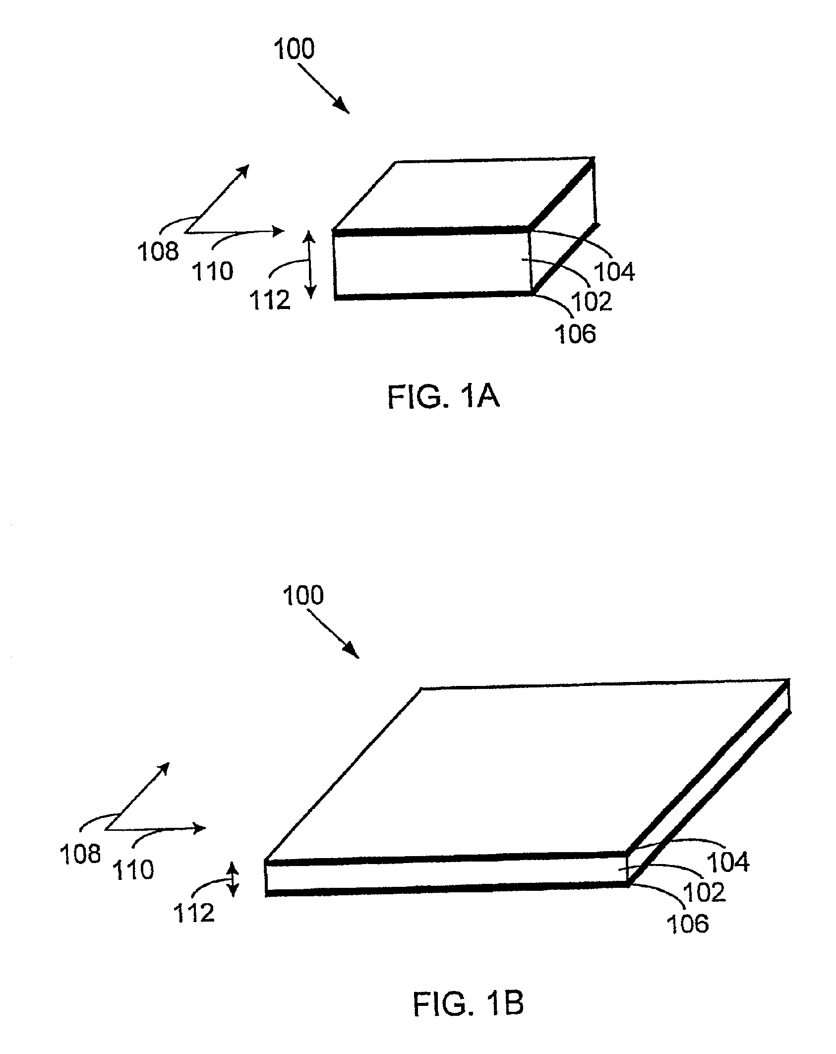
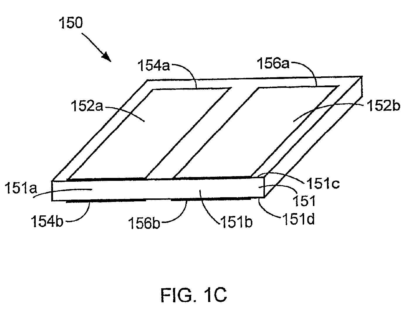
[0037]In one aspect, the present invention relates to continuous output systems that include one or more electroactive polymer transducers. When actuated, a transducer of the present invention produces deflection in one or more directions. Repeated actuation of the transducer may produce reciprocating motion. Reciprocating motion of a transducer may be converted to continu...


PUM


Abstract

The present invention relates to mechanical-electrical power conversion systems. The systems comprise one or more electroactive polymers that convert between electrical and mechanical energy. When a voltage is applied to electrodes contacting an electroactive polymer, the polymer deflects. This deflection may be converted into rotation of a power shaft included in a motor. Repeated deflection of the polymer may then produce continuous rotation of the power shaft.

Description

CROSS-REFERENCE TO RELATED APPLICATION[0001]This application claims priority under 35 U.S.C. §119(e) from now abandoned, U.S. Provisional Patent Application No. 60 / 273,108, filed Mar. 2, 2001 which is incorporated by reference for all purposes.BACKGROUND OF THE INVENTION[0002]The present invention relates generally to motors comprising one or more electroactive polymers. More particularly, the present invention relates to clutch motors and their use in various applications.[0003]A motor converts from an input energy to mechanical energy. Most often, the mechanical energy is output as rotary motion of a shaft, but linear motors for translating a shaft are also commonly used. The most common class of input energy for a motor is electricity. Electric motors include AC, DC, servo, and stepper motors. Compressed air and pressurized hydraulic fluid are also used to power air and hydraulic motors. Gasoline or diesel engines are another traditional class of motors that rely on combustion of...

Claims


Application Information

Patent Timeline
Patent Type & Authority Patents(United States)
IPC IPC(8): H01L41/08H01L41/09
CPCH02N2/101H01L41/0986Y10S310/80H10N30/206
Inventor HEIM, JONPELRINE, RONALD E.KORNBLUH, ROY D.ECKERLE, JOSEPH STEPHEN
Owner SRI INTERNATIONAL
Why Eureka
Try Eureka