

Magnetic head actuator having finely movable tracking device
a tracking device and head actuator technology, applied in the direction of maintaining head carrier alignment, printed circuit non-printed electric components association, instruments, etc., can solve the problems of continuity defects, high cost easy breakage of au wire bonding, so as to facilitate wiring to the piezoelectric element, the effect of reducing continuity defects and wire breakag
- Summary
- Abstract
- Description
- Claims
- Application Information
AI Technical Summary
Benefits of technology
Problems solved by technology
Method used
Image

Examples
first embodiment
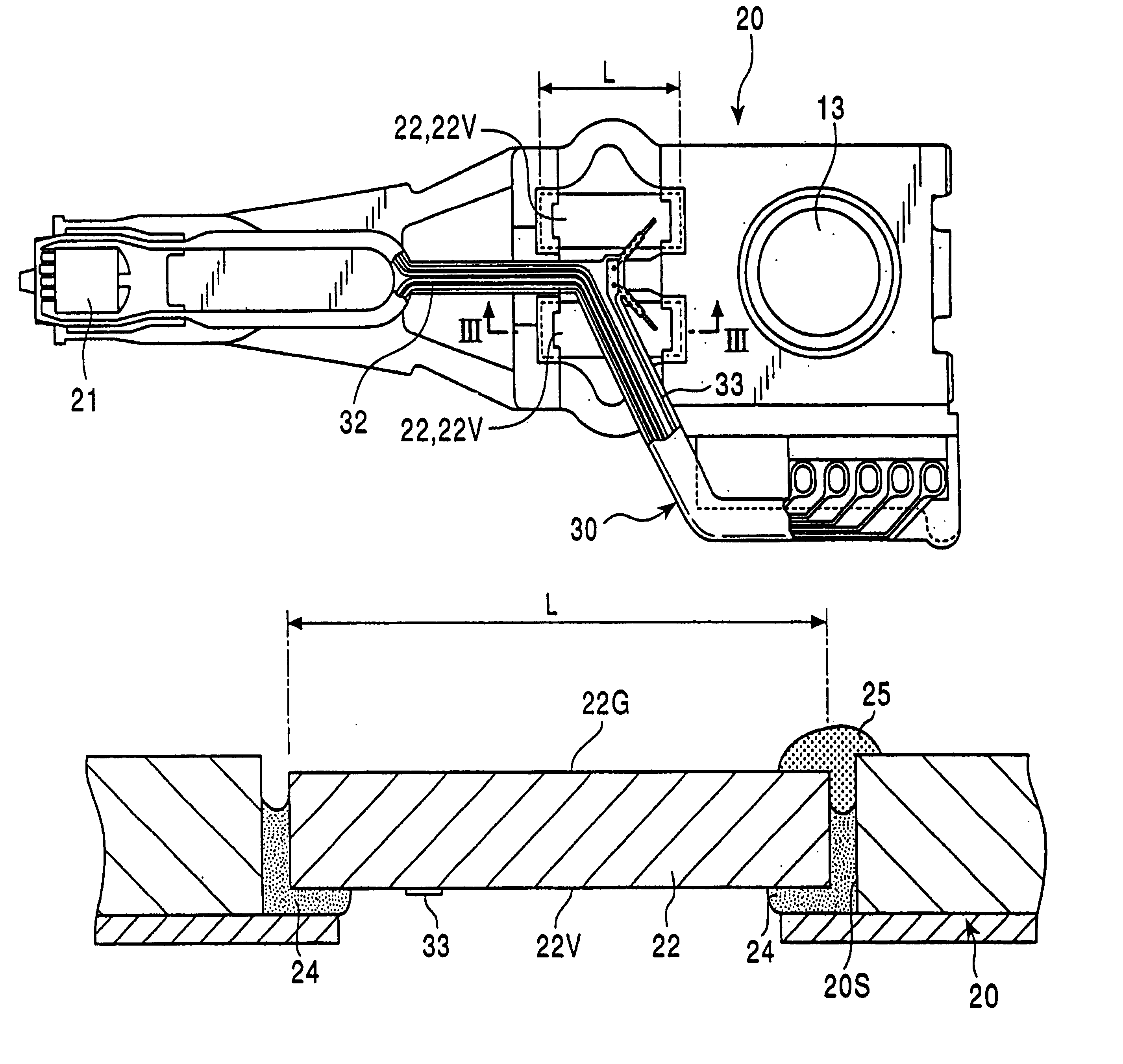
[0042]FIGS. 4 to 9 illustrate the present invention. The FPC board 30, having the resin base 31 and the feeding lines 33, is arranged to extend onto the voltage-impressing electrodes 22V of the piezoelectric elements 22. The feeding lines 33 are partially exposed by removing the resin base 31 from the portion of feeding lines 33 that extend onto the voltage-impressing electrodes 22V. The feeding lines 33 are typically composed of copper (Cu) and have gold plating layers 34 on the exposed portions of the front and back surfaces of the feeding lines 33. The resin base 31 and the feeding lines 33 both extend onto the voltage-impressing electrodes 22V and are held on the side of the FPC board 30 until the feeding line 33 is connected to the piezoelectric element 22. The feeding lines 33 have a thickness of, for example, about 10 to about 20 μm.
[0043]In this embodiment, the feeding line 33 of the FPC board 30 abuts against the voltage-impressing electrode 22V, and an ultrasonic probe 41 ...
third embodiment
[0045]FIGS. 13 to 17 illustrate the present invention. The feeding line 33, embedded in the resin base 31 of the FPC board 30, is partially exposed at the upper and lower portions of the feeding line 33 that extend onto the voltage-impressing electrode 22V of the piezoelectric element 22. In this embodiment, the resin base 31 at the end of the feeding line 33 is partially removed in a round form so as to leave a remaining ring 31A on the front and back surfaces of the feeding line 33. The resin removed portion is thereby surrounded by the remaining ring 31A. The resin base 31, typically formed of a polyamide resin, covers and reinforces the feeding line 33 other than the inside of the remaining ring 31A. In this configuration, the feeding line 33 is rarely broken without exerting an external force. The feeding line 33 has a through-hole 33A inside the remaining ring 31A. A remaining portion is not necessarily circular; however, it is advantageous from the viewpoint of strength that ...
fourth embodiment
[0047]FIGS. 18 and 19 illustrate the invention, bonding the feeding line 33 and the voltage-impressing electrode 22V is completed by stud bumping instead of Au ball bonding. The voltage-impressing electrode 22V has a stud bump 45 thereon that is accreted in advance of bonding by discharging a gold ball. The stud bump 45 consists of a large diameter portion 45a firmly bonded to the voltage-impressing electrode 22V, and a small diameter portion 45b formed on the large diameter portion 45a. The shape of the stud bump 45 is determined depending on the shape of a capillary for a gold ball.
[0048]The feeding line 33 of the FPC board 30 and the voltage-impressing electrode 22V are bonded as follows. After the small diameter portion 45b of the stud bump 45 is inserted into the through-hole 33A of the feeding line 33, an ultrasonic probe is brought into contact on the small diameter portion 45b so as to crush the small diameter portion 45b. In accordance with this embodiment of the invention,...
PUM
 Abstract
Description
Claims
Application Information