Method, system, and apparatus for detecting a position of a terminal in a network

a terminal and network technology, applied in the field of position locating methods, can solve the problems of requiring a certain level of accuracy and difficult reception of terminal services, and achieve the effect of reducing the difficulty of terminals receiving such services

Inactive Publication Date: 2007-01-23
HITACHI LTD
View PDF19 Cites 39 Cited by
  • Summary
  • Abstract
  • Description
  • Claims
  • Application Information

AI Technical Summary

Benefits of technology

[0007]Under the circumstances, the present invention aims to provide a method for locating positions of a terminal of a wireless LAN system accurately without providing the terminal with a GPS receiver.

Problems solved by technology

In this case, the terminal will be difficult to receive such services as the “navigation services”, which requires a certain level of accuracy.

Method used


Image

  • Method, system, and apparatus for detecting a position of a terminal in a network
  • Method, system, and apparatus for detecting a position of a terminal in a network
  • Method, system, and apparatus for detecting a position of a terminal in a network

Examples


third embodiment

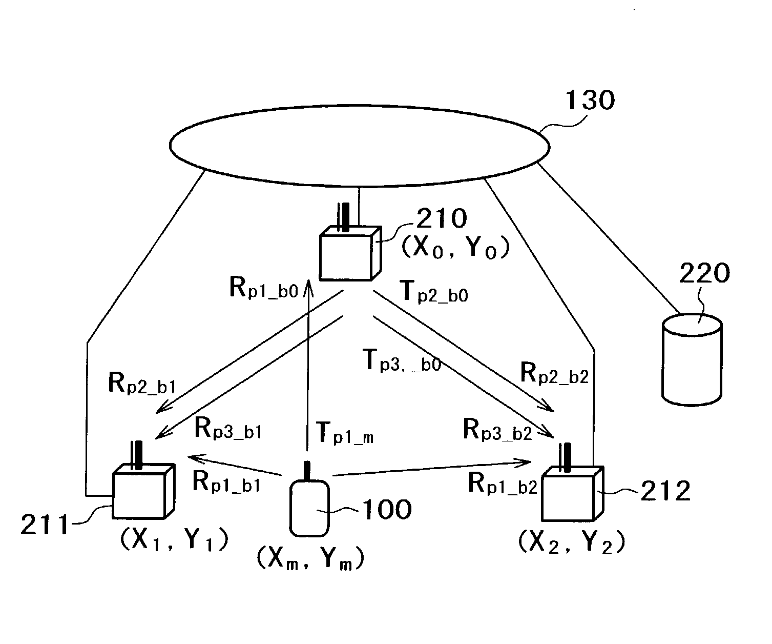
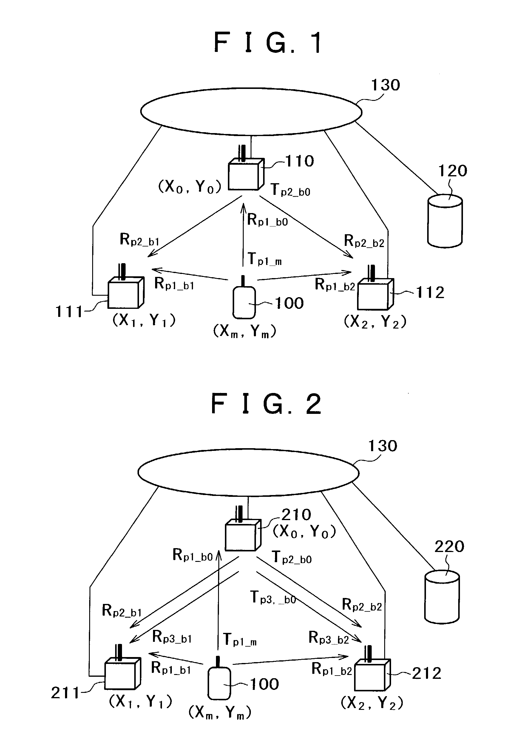
[0076]In this third embodiment, three base stations are used to calculate the two-dimensional position of the terminal 100 to simplify the description. However, the number of base stations used for the calculation is not limited only to three; N base stations (N≧4) may be used. In this connection, expressions 1 to 3 may be used as (i=1,2, . . . N−1). Expressions 4 to 6 may be used as (k=1,2, . . . N). The equation in the expression 1 or 4 can be solved by, for example, the least square method. The “position calculating method and position calculating apparatus” disclosed in JP-A No.236163 / 2002 may also be used to calculate the position of the terminal 100 more accurately. The method for calculating the two-dimensional position of the terminal 100 is also included in the invention. In this connection, the z coordinate is added to the expressions 1 to 3 with respect to the N base stations (N≧4) to form the expressions as (i=1,2, . . . ,N−1) or the z coordinate is added to the expressi...

second embodiment

[0110]Even when the clock accuracy varies among base stations and the clock error changes with time in those base stations, the invention is effective to suppress the degradation of the locating accuracy to be caused by a clock error.

[0111]If both sending and receiving delay times in each base station are decided beforehand, both sending and reception timings of each wireless packet can be measured more accurately. If the transmission power in the frequency channel selected for position locating is controlled so as to be reduced in each of the base stations positioned around the base station selected for position locating, the interference by signals can be reduced, thereby the wireless packet reception timing measurement accuracy is more improved and the position locating accuracy is improved.

[0112]Furthermore, according to the embodiments of the invention, it is possible to synchronize base stations with each other at a time accuracy equally to the position locating accuracy.

[0113...


PUM


Abstract

A method, system, and apparatus are provided for detecting a position of a terminal in a network accurately without a GPS receiver. In one example, a method for locating a position of a terminal includes calculating a position of a base station; detecting a clock time difference between the base station and another base station; measuring a reception timing of a signal received by the base station from the terminal; and locating the position of the terminal using at least the position of the base station, the clock time difference, and the reception timing.

Description

COPYRIGHT NOTICE[0001]A portion of the disclosure of this patent document contains material which is subject to copyright protection. The copyright owner has no objection to the facsimile reproduction by anyone of the patent document or the patent disclosure, as it appears in the Patent and Trademark Office patent file or records, but otherwise reserves all copyright rights whatsoever.BACKGROUND OF THE INVENTION[0002]1. Field of the Invention[0003]The present invention generally relates to a position locating method employed for wireless communications and, more particularly, to a position locating method for wireless local area network (LAN) systems.[0004]2. Discussion of Background[0005]The wireless LAN defined typically by the IEEE802.11 Standard is now employed widely in offices and public spaces such as hot spots due to its properties of compatibility with the Internet and fast data transfer with wide-ranged wireless media (semi-micro waves, semi-millimeter waves, infrared rays...

Claims


Application Information

Patent Timeline
Patent Type & Authority Patents(United States)
IPC IPC(8): H04Q7/20G01S5/00G01S5/06H04L12/28H04W56/00H04W64/00
CPCH04W64/00G01S5/06G01S5/0054G01S5/0081G01S5/021G01S5/02216
Inventor OGINO, ATSUSHIYANO, TAKASHITSUNEHARA, KATSUHIKOYAMASAKI, RYOTASHIDA, MASAAKISUZUKI, HIDEYADOI, NOBUKAZU
Owner HITACHI LTD
Why Eureka
Try Eureka