Electrical muscle controller

Inactive Publication Date: 2007-01-23
IMPULSE DYNAMICS NV
View PDF169 Cites 69 Cited by
  • Summary
  • Abstract
  • Description
  • Claims
  • Application Information

AI Technical Summary

Benefits of technology

[0213]Preferably, the field reduces the reactivity of the portion to an activation signal.

Problems solved by technology

The cell may also be totally blocked from reacting by maintaining a sufficiently positive voltage to the outside of the cell, so that an activation signal fails to sufficiently depolarize the cellular membrane.
A pacema

Method used


Image

  • Electrical muscle controller
  • Electrical muscle controller
  • Electrical muscle controller

Examples


Example

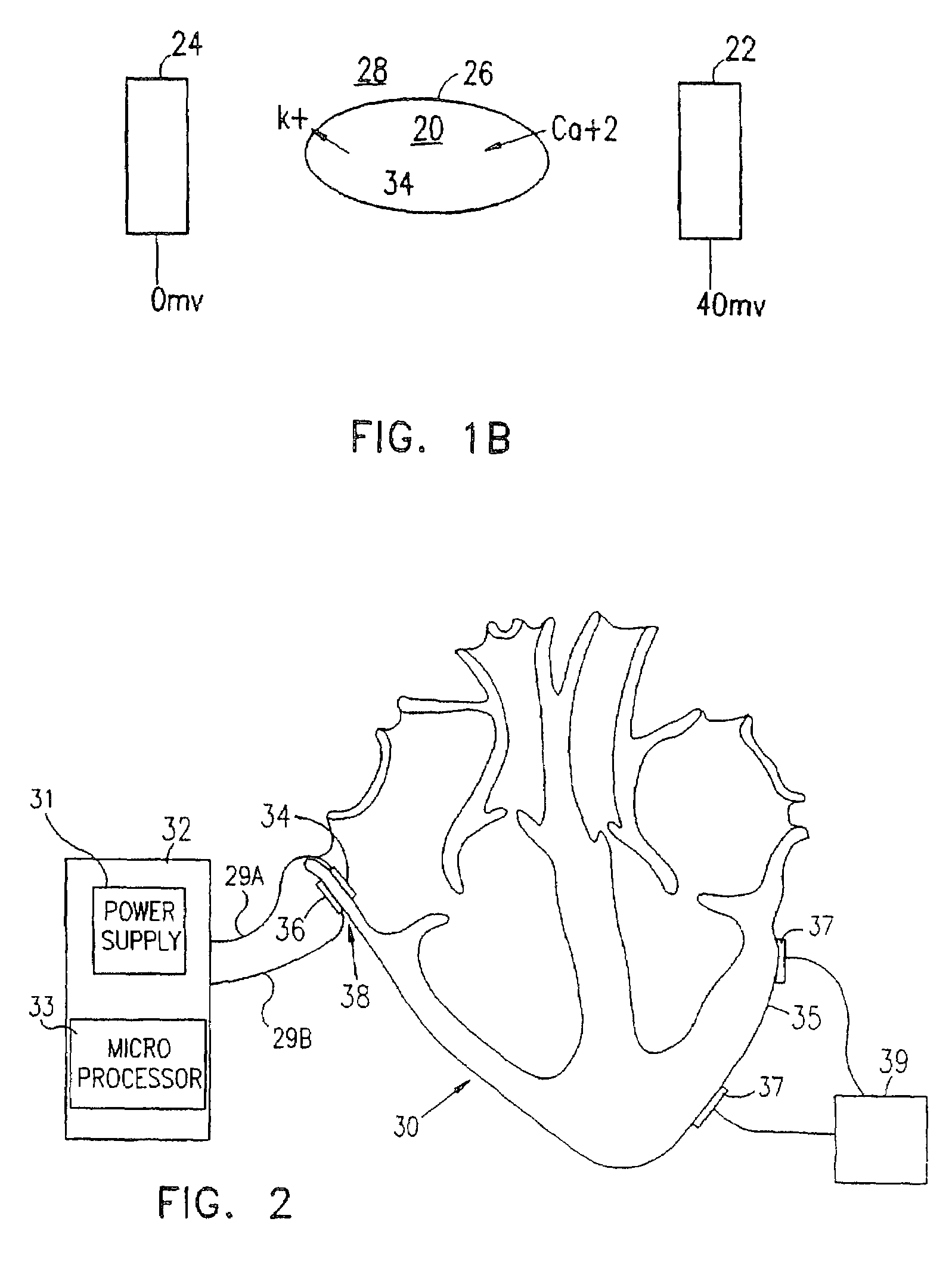
[0418]One aspect of the present invention relates to controlling and / or modulating the contractility of a cardiac muscle segment and / or the plateau duration of an action potential of the cardiac muscle segment, by applying an electric field or current across the segment. As used herein, the terms, voltage, electric field and current are used interchangeably to refer to the act of supplying a non-excitatory signal to control cardiac activity. The actual method of applying the signal is described in more detail below.

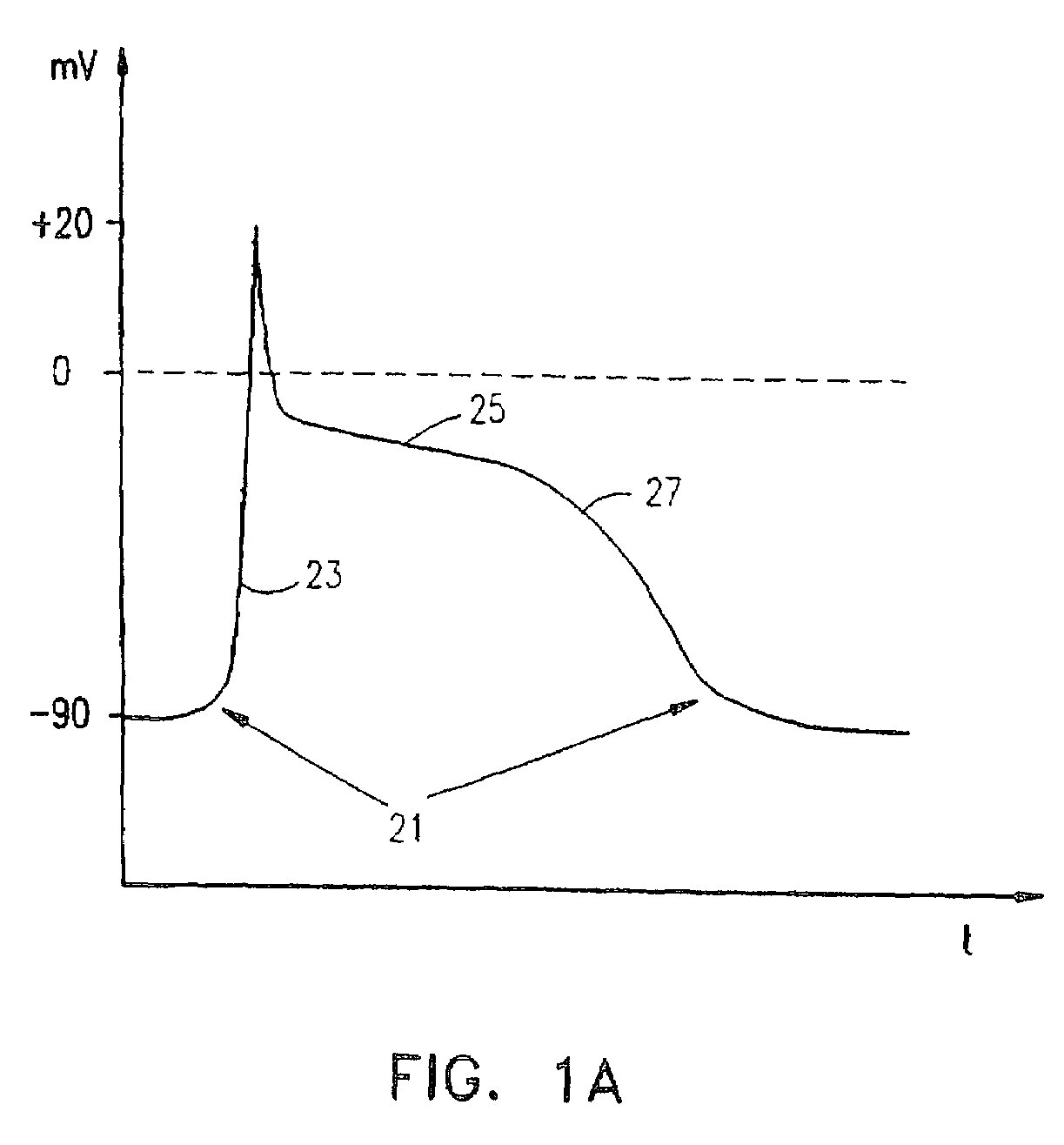
[0419]FIG. 1B shows a schematic model illustrating one possible explanation for the relation between an applied voltage and a resulting plateau duration. A cell 20, having a membrane 26, surrounded by extra-cellular fluid 28, is located in an electrical field generated by an electrode 22 and an electrode 24. Cell 20 has a −40 mV internal potential across membrane 26, electrode 22 has a potential of 40 mV and electrode 24 is grounded (to the rest of the body). During the a...


PUM


Abstract

A method of modifying the force of contraction of at least a portion of a heart chamber, including providing a subject having a heart, comprising at least a portion having an activation, and applying a non-excitatory electric field having a given duration, at a delay after the activation, to the portion, which causes the force of contraction to be increased by a least 5%.

Description

RELATED APPLICATIONS[0001]This application is a continuation of commonly assigned U.S. patent application Ser. No. 10 / 001,700, filed Oct. 31, 2001 now U.S. Pat. No. 7,062,318, which is a continuation of U.S. patent application Ser. No. 09 / 723,989, filed Nov. 28, 2000 now U.S. Pat. No. 6,330,476, which is a continuation of commonly assigned U.S. patent application Ser. No. 09 / 101,723, filed Aug. 13, 1998, now U.S. Pat. No. 6,317,631, incorporated herein by reference, which is a National Phase of PCT Patent Application No. PCT / IL97 / 00012, filed Jan. 8, 1997, which is related to the following U.S. and Israeli applications, the disclosures of which are also incorporated herein by reference: U.S. Provisional patent application No. 60 / 009,769, filed Jan. 11, 1996, Israel patent application No. 116,699, filed Jan. 8, 1996, U.S. Provisional patent application No. 60 / 011,117, filed Feb. 5, 1996, Israeli patent application No. 119,261, filed Sep. 17, 1996, U.S. Provisional Application No. 60 / ...

Claims


Application Information

Patent Timeline
IPC IPC(8): A61N1/362A61B5/00A61B5/0215A61B5/029A61B5/042A61B5/06A61B17/00A61B17/02A61B18/20A61N1/32A61N1/36A61N1/365A61N1/368
CPCA61B5/0215A61B5/0422A61B5/06A61B5/14503A61B5/6843A61B5/6852A61B5/6853A61B5/6856A61B5/6858A61B5/6859A61B18/20A61N1/32A61N1/362A61N1/3627A61N1/36514A61N1/36564A61B5/029A61N1/36146A61B5/14539A61B5/4519A61B2017/00243A61B2017/00247A61B2017/0243A61B2018/00392A61M2025/0166A61N1/326A61N1/3621A61N1/365A61N1/36557A61N1/368A61B5/287
Inventor BEN-HAIM, SHIOMODARVISH, NISSIMFENSTER, MAIERYUVAL, MIKA
Owner IMPULSE DYNAMICS NV
Why Eureka
Try Eureka