Flight management system and method for providing navigational reference to emergency landing locations

a flight management system and emergency landing technology, applied in the field of navigational flight management systems, can solve problems such as emergency landing airports, and achieve the effect of maximizing safety

Inactive Publication Date: 2007-01-23
CONTROL VISION CORP
View PDF7 Cites 31 Cited by
  • Summary
  • Abstract
  • Description
  • Claims
  • Application Information

AI Technical Summary

Benefits of technology

[0014]The present invention provides a flight management system and method capable of providing the pilot with a real time display of various landing locations within gliding range in a format that assists the pilot in evaluating both present and future course options thereby maximizing safety. The present invention provides an improvement to known flight management systems by simultaneously displaying gliding range information for a number of alternate landing locations thereby providing the pilot with current and future emergency landing options in the event of sudden engine failure.
[0015]The present invention presents information to the pilot by complementing the flight management system's conventional moving map display with airports and other landing locations enhanced to include circular symbols centered on each landing location. Each circular symbol represents a sectional view of an imaginary inverted cone, having the apex thereof centered on its respective airport. The size and shape of the cone is based on the gliding performance of the aircraft and the altitude differential between the aircraft and that particular landing location. As the altitude differential increases the radius of the circle increases. Conversely as the altitude differential decreases, the radius of the circle decreases. Each three dimensional inverted cone is represented as a circle having the airport at the center for each airport displayed. As long as the aircraft is anywhere within any one of the three-dimensional inverted cones displayed, as represented by one or more circles on a two dimensional display, it can safely glide to the landing location. This display concept is selectively referred to herein as “cones of safety.” The present invention thus provides a flight management system that generates and displays cones of safety for each landing location, e.g. airport and / or landing strip, appearing on the flight management display. By displaying glide range information in this manner the pilot is better able to plot a course that maximizes time within cones of safety.
[0017]The present invention maintains real time representations of cones of safety for each landing location displayed on a GPS / GIS enabled dynamic navigational map generated by the flight management system. Thus, unlike glide range displays that are centered on the aircraft as disclosed in the background art, the present invention generates circular glide range displays that are centered on each potential landing area. If the aircraft is operating in an area of overlapping glide range circles, then multiple options are available for an emergency landing as the aircraft is within gliding range of each airport associated with the overlapping cones of safety. In addition, a significant improvement is realized in that by simultaneously displaying cone of safety information for each potential landing location, the pilot is able to chart a course that maximizes emergency landing options. By referencing the various cones of safety displayed, the pilot is able to execute a flight plan having a course that maximizes the flight time within cones of safety thus maximizing emergency landing options while minimizing flight time void of emergency landing options. Thus, the pilot is provided with advance warning if the projected course does not intersect cones of safety and is thus void of emergency landing airports. As should be apparent, providing such useful information in advance allows the pilot to maximize safety by altering course so as to maximize flight time within one or more cones of safety.
[0018]Accordingly, it is an object of the present invention to provide an improved flight management system.

Problems solved by technology

Thus, the pilot is provided with advance warning if the projected course does not intersect cones of safety and is thus void of emergency landing airports.

Method used


Image

  • Flight management system and method for providing navigational reference to emergency landing locations
  • Flight management system and method for providing navigational reference to emergency landing locations
  • Flight management system and method for providing navigational reference to emergency landing locations

Examples


Embodiment Construction

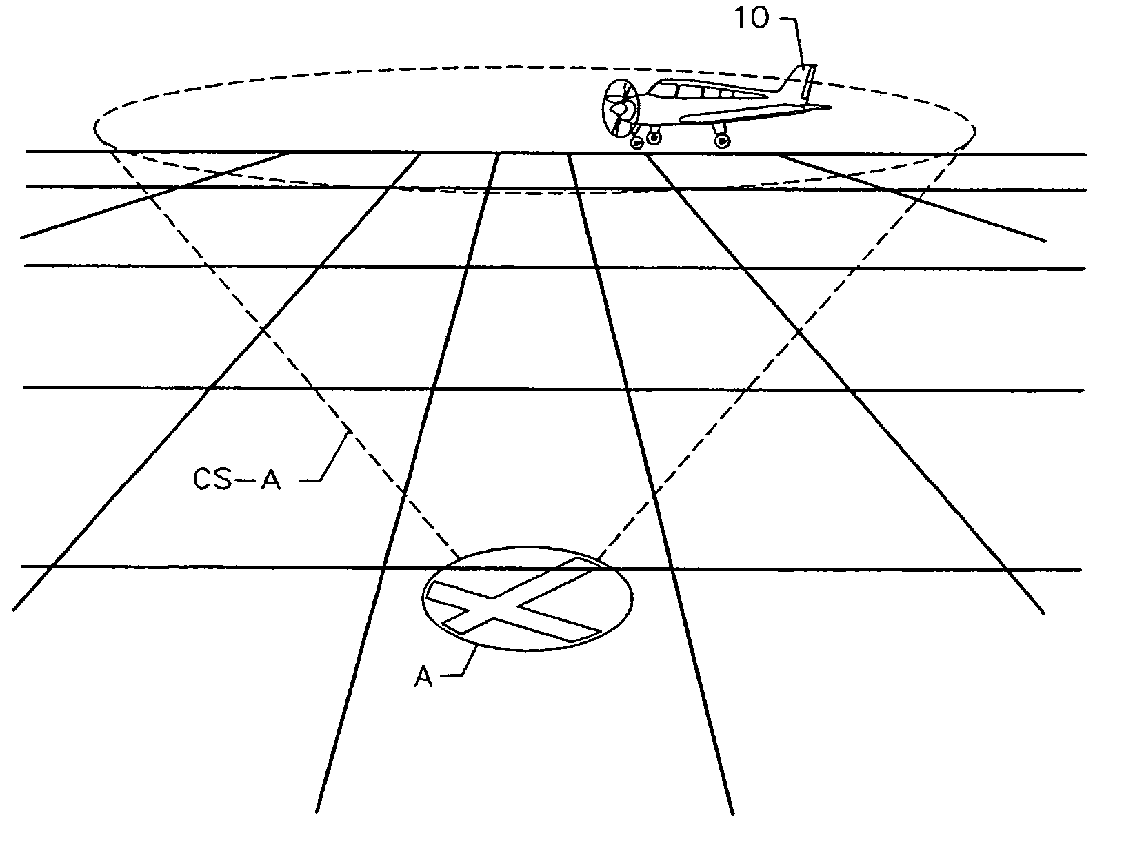
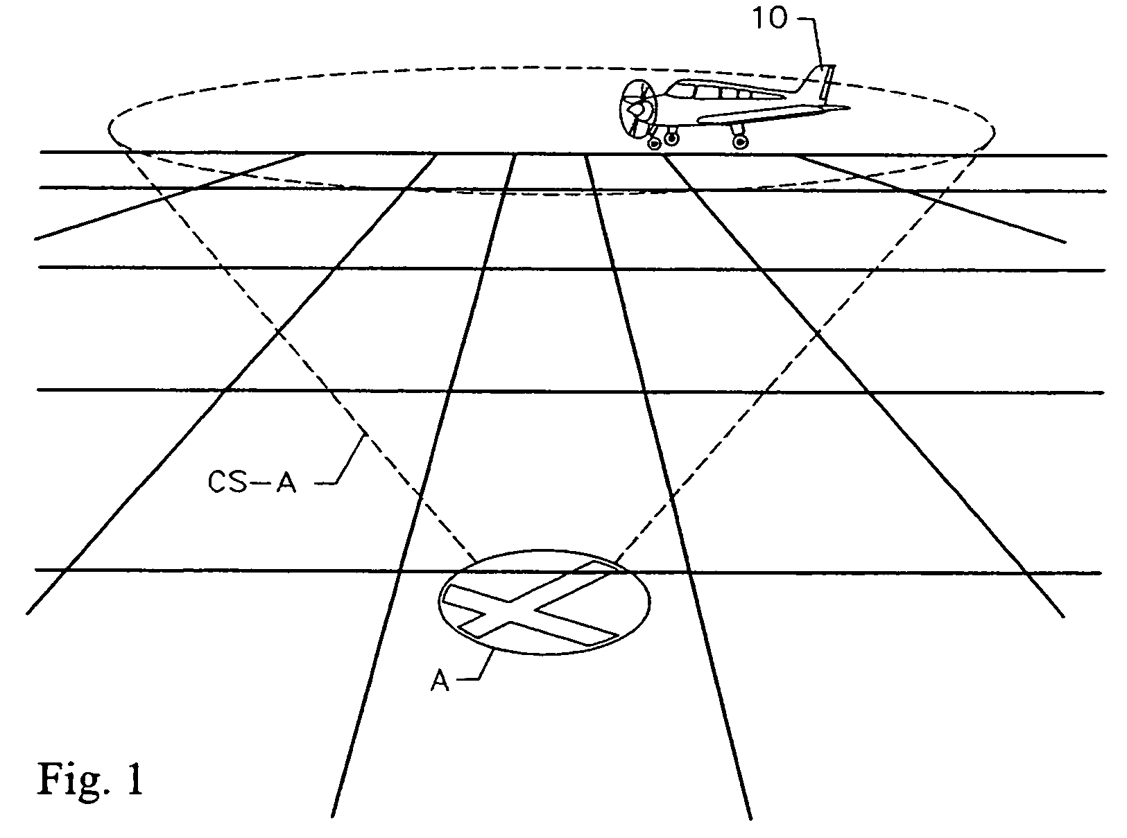
[0027]With reference now to the drawings, FIGS. 1–5 illustrate a flight management system in accordance with the present invention. The flight management system includes an electronic display enabled with moving map GPS navigational data adapted to calculate and display “cones of safety” for various airports along the flight route. FIG. 1 depicts an aircraft relative to an airport with the cone of safety depicted in phantom view to illustrate the cones of safety concept. The present invention provides a flight management system and method capable of providing the pilot with a moving map display depicting the locations of multiple airports, which locations are complemented with glide range identification symbology to assist the pilot in evaluating both present and future course options thereby enabling the pilot to execute a flight plan wherein the availability of emergency landing locations is maximized.

[0028]The cone of safety method is suitable for use with a wide variety of elect...


PUM


Abstract

An aviation navigational system and method for predicting glide range for an aircraft for specific airports and other potential emergency landing locations in proximity to the aircraft. Information is presented to the pilot by complementing a conventional moving map display with symbols centered on each landing location. GPS altitude, airport elevation, and the aircraft's glide ratio are factored into an equation to determine glide range for each airport within proximity to the aircraft. A circular symbol representing the glide range boundary is displayed around each airport. Each circular symbol represents a sectional view of an imaginary inverted cone, having the apex thereof centered on a given landing location. The size and shape of the cone is based on the gliding performance of the aircraft and the altitude differential between the aircraft and the target landing location. As the altitude differential increases the radius of the circle increases. Conversely as the altitude differential decreases, the radius of the circle decreases. As long as the aircraft is anywhere within any one of the three-dimensional inverted cones displayed, as represented by one or more circles on a two dimensional display, it can safely glide to the landing location. This display concept is selectively referred to herein as “cones of safety.”

Description

CROSS REFERENCE TO RELATED APPLICATIONS[0001]This application claims the benefit of provisional U.S. Patent Application No. 60 / 299,261, filed Jun. 19, 2001.STATEMENT REGARDING FEDERALLY SPONSORED RESEARCH OR DEVELOPMENT[0002]N / ACOPYRIGHT NOTICE[0003]A portion of the disclosure of this patent document contains material that is subject to copyright protection. The copyright owner has no objection to the facsimile reproduction by anyone of the patent document or patent disclosure as it appears in the Patent and Trademark Office patent file or records, but otherwise reserves all copyrights.BACKGROUND OF THE INVENTION[0004]1. Field of the Invention[0005]The present invention relates to aviation navigation and flight management systems, and more particularly to a navigational flight management system and method for dynamically displaying airports in proximity to the aircraft along with glide range symbology for each airport.[0006]2. Description of the Background Art[0007]Various aviation ...

Claims


Application Information

Patent Timeline
Patent Type & Authority Patents(United States)
IPC IPC(8): G06F11/30G08G7/00G01C23/00G08G5/02
CPCG01C23/00G08G5/025G08G5/0056G08G5/0021G08G5/0039
Inventor HUMBARD, JOHN JAYPUTMAN, JOSEPH
Owner CONTROL VISION CORP
Why Eureka
Try Eureka